
TD1 Dual Wire Feeder Operator Manual #
TD1 Wire Feeder — Accessory to the THEO MA1 Series Handheld Laser Welder
Please read and understand all instructions before use.
Guarde este manual para consulta futura.
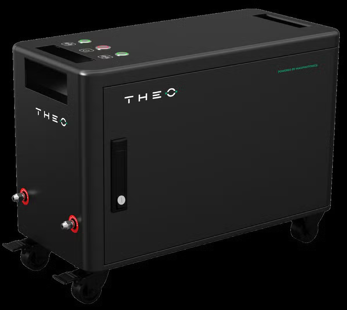
THEO TD1 Dual Wire Feeder #
Aviso Legal n. º
Editor, Fabricante e Representantes Autorizados #
This Operator Manual is published by Maxphotonics GmbH on behalf of Maxphotonics Co., Ltd. (Shenzhen, China), the manufacturer of the TD1 Dual Wire Feeder. THEO Laser is a brand of Maxphotonics GmbH.
Fabricante
Maxphotonics Co., Ltd.
Maxphotonics Industrial Park, Third Furong Road, Furong Industrial Area, Shajing, Bao’an, Shenzhen, China 518125
Phone: +86 400-900-9588
Web: https://www.maxphotonics.com
Representante autorizado na UE
MAXPHOTONICS GmbH
Dornierstraße 11, 82205 Gilching, Germany
Phone: +49 (0) 8105 7303890
Email: emea@maxphotonics.com
Authorized by Maxphotonics Co., Ltd. pursuant to Article 2(j) of Directive 2006/42/EC and Article 4 of Regulation (EU) 2023/1230 (applicable from 20 January 2027).
Importador dos Estados Unidos
THEO Laser Inc.
1900 West Park Dr., Suite #150, Westborough, MA 01581, USA
Web: https://theo.inc
Aviso legal n.º #
At THEO, we are committed to providing accurate and reliable information in this manual. However, we make no warranties, either expressed or implied, regarding the completeness or suitability of the content for specific applications. This includes, but is not limited to, implied warranties of merchantability or fitness for a particular purpose.
Users bear full responsibility for how the product is applied. THEO shall not be held responsible for any incidental, indirect, or consequential damages such as loss of profits or production, or any other costs arising from the use of this manual.
Some information may potentially infringe on patents or third-party rights. THEO assumes no liability for such infringements or for any damages caused by inaccuracies or omissions in this document.
Nothing in this Disclaimer limits or excludes any liability that cannot be limited or excluded under applicable law, including liability for death or personal injury caused by negligence, fraud or fraudulent misrepresentation, or any statutory liability under applicable product liability law (such as Directive 85/374/EEC as revised by Directive (EU) 2024/2853, or equivalent national law). Consumers and users in the European Union / EEA may have additional statutory rights that are not affected by this Disclaimer.
Copyright Notice #
© Maxphotonics Co., Ltd. (hereinafter referred to as Maxphotonics). All rights reserved. No part of this manual may be copied, reproduced, transmitted, transcribed, stored in a retrieval system, or translated into any language or computer language, in any form or by any means, without the prior written permission of Maxphotonics.
THEO, Maxphotonics, and their logos are registered trademarks of Maxphotonics Co., Ltd. Use of these marks is governed by our trademark policy.
All information is subject to change without notice. The English version is the original and authoritative version of this manual; where it is translated into another language, the English version shall prevail in the event of any inconsistency.
EU Declaration of Conformity and CE Marking #
The TD1 Dual Wire Feeder bears the CE marking. An EU Declaration of Conformity has been drawn up by the manufacturer in accordance with Directive 2006/42/EC (Machinery), as applicable, and with the EMC Directive 2014/30/EU.
Harmonized standards applied include (in whole or in part): EN ISO 12100 (safety of machinery — general principles for design), EN 60204-1 (electrical equipment of machines), EN 55011 (industrial radio-disturbance emissions), and EN IEC 61000-6-2 (immunity for industrial environments).
A copy of the EU Declaration of Conformity is available from the EU Authorized Representative on request and is provided with each unit shipped to EU/EEA destinations.
RoHS and WEEE (EU / EEA) #
This product complies with Directive 2011/65/EU (RoHS) as amended, restricting the use of certain hazardous substances in electrical and electronic equipment.
Do not dispose of this product as unsorted municipal waste. In accordance with Directive 2012/19/EU (WEEE), at end of life this equipment shall be collected separately for recovery and recycling through the take-back systems available in your country. Contact your local dealer or the EU Authorized Representative for return information.
FCC Notice (USA) #
This equipment has been tested and found to comply with the limits for a Class A digital device, pursuant to Part 15 of the FCC Rules. These limits are designed to provide reasonable protection against harmful interference when the equipment is operated in a commercial environment. This equipment generates, uses, and can radiate radio frequency energy and, if not installed and used in accordance with the instruction manual, may cause harmful interference to radio communications. Operation of this equipment in a residential area is likely to cause harmful interference, in which case the user will be required to correct the interference at their own expense.
California Proposition 65 Warning (USA) #
⚠ WARNING: This product and/or the welding process it supports can expose you to chemicals, including nickel and chromium compounds, which are known to the State of California to cause cancer and reproductive harm. For more information, go to P65Warnings.ca.gov.
Prerequisite — Host Welder Manual #
The TD1 Dual Wire Feeder is an accessory to the MA1 series handheld laser welder. It is designed and approved for use exclusively with the MA1 series and must be used together with an MA1 series welder that is in full compliance with its own Operator Manual and applicable regulations.
The TD1 does not emit laser radiation. All laser-related safety information — including laser class, nominal ocular hazard distance (NOHD), personal protective equipment (PPE) selection, protective enclosure requirements, and laser-safety officer duties — is contained in the MA1 series Operator Manual and shall be observed in full when the TD1 is connected to the MA1.
Before operating the TD1, the operator must have read, understood, and be trained on the current MA1 series Operator Manual (see the MA1 Operator Manual on theo.inc). Where a requirement in this TD1 manual is stricter than the MA1 manual, the stricter requirement applies.
1. Overview #
1.1. Introduction #
Thank you for choosing THEO’s TD1 Dual Wire Feeder. This user manual provides you with important safety, operation, maintenance, and warranty information. Please read carefully before installation and use, and keep this manual for future reference.
To ensure operational safety and product operation in optimal condition, please follow the precautions and warnings listed in this manual. Failure to observe these precautions and warnings may result in personal injury or damage to the equipment.
This manual covers a general description of the basic installation, operation and maintenance of the welding wire feed part. For information about the host laser welder, refer to the current MA1 series Operator Manual.
The TD1 Dual Wire Feeder is mainly used where wire fed welding is required or the weld is large. The TD1 boasts additional benefits including improved welding stability, appearance, formability, greater capacity, and increased efficiency compared to manual wire feeding.
1.2. Safety Precautions and Warning Symbols #
This section outlines the types of potential hazards associated with the product and how to avoid them. Each warning includes:
- A signal word with a colored symbol indicating the level of warning
- A concise explanation of the hazard or instruction
Signal Words #

|
PERIGO
Indicates an immediate hazard that will cause severe injury or death if it is not avoided. |
|
|
AVISO
Points to a potential hazard that could lead to serious injury or fatality if not properly addressed. |
|
|
ATENÇÃO
Highlights situations where minor or moderate injury may occur. |

|
NOTE
Used for situations that may result in damage to the equipment or property, but do not directly cause personal injury. |
|
|
AVISO
Indicates important information not related to hazards, such as tips or reminders. |
Simplified safety instructions or warnings may also be used as long as they remain clear and understandable. These typically appear as short text alerts near the referenced action or component.
|
|
NOTE
This equipment is not intended for use in residential environments and may not provide adequate protection to radio reception in such environments. Per EN 55011 Clause 6.2, installation and operation in industrial environments only. |
1.3. Parameters and Features #
| Specification | TD1 Wire Feeder |
|---|---|
| Supply Voltage | DC 24 V |
| Environmental Setting | Smooth, no vibration, no impact |
| Operating Ambient Temperature | 0 to 40 °C (32 to 104 °F) |
| Storage Ambient Temperature | -20 to 55 °C (-4 to 131 °F) |
| Relative Humidity | ≤ 90% (non-condensing) |
| Wire Feed Speed | 2 to 50 mm/s |
| Retract Speed | 2 to 100 mm/s |
| Manual Wire Feed / Retract Speed | Less than 0 to 100 mm/s |
| Welding Wire Diameter | 1.2 / 1.6 mm |
| Overall Dimensions (L × W × H) | 580 mm × 433.5 mm × 270 mm |
| Ingress Protection | IP20 |
| Peso | Refer to product label |
| Compliance | CE (Machinery, EMC), RoHS, WEEE, FCC Part 15 Class A |
|
|
NOTE
The wire feed wheel matches the diameter of the wire and corresponds to the wire feeding tube. Do not mix diameters or roller types. |
1.4. Dimensions with Wheel #
580 mm × 433.5 mm × 270 mm (L × W × H)

Figure 1 — TD1 outer dimensions (mm) with wheel.
1.5. Intended Use, Foreseeable Misuse and Residual Risks #
Intended use. The TD1 Dual Wire Feeder feeds one or two solid welding wires into the weld pool of an MA1 series handheld laser welder during manual laser welding operations in industrial environments. It is intended for use by trained industrial operators.
Foreseeable misuse — not intended for: (a) use with any laser welder other than the MA1 series; (b) use with coated, cored, flux-cored, or aluminized wires outside the wire types and diameter range specified in §1.3; (c) outdoor use, use in explosive atmospheres (ATEX/IECEx zones), use in wet locations, or use in medical, aerospace, or safety-critical applications; (d) modification of the wire drive, housing, electrical circuits, or safety interlocks; (e) operation by personnel not trained on the MA1 series laser welder.
Residual risks. Even when used as intended, the following risks remain and are addressed by the precautions in Chapter 2: mechanical pinch / crush at the drive rolls; thermal burn from feed tube and wire tip; eye and skin exposure from the MA1 laser beam (see MA1 manual); arc and weld spatter; inhalation of welding fume; electrical hazards from the MA1 power source.
2. Installation #
2.1. General Definition of Circuit Connection #

Figure 2 — 7-pin connector pinout.
| Pin | Definição |
|---|---|
| 1-2 Pins | DC 24 V |
| 3 Pins | Signal input / low level is active |
| 4 Pins | Reserved |
| 5 Pins | Reserved |
| 6 Pins | Reserved |
| 7 Pins | Reserved |
2.2. External Wiring Method of Wire Feeder #
The wire feeder system connects the following components:
- Power Supply → Power Cord → Wire Feeder
- Gas Cylinder → Gas Tube → THEO handheld laser welder
- Wire Feeder → Communication Cable → THEO handheld laser welder
- Wire Feeder → Wire Feed Tube → Welding Torch → Work Piece
- Safety Loop connects the welding torch circuit

Figure 3 — External wiring: TD1 wire feeder, MA1 handheld laser welder, gas cylinder, and torch.
2.2.1. Electromagnetic Compatibility (EMC) #
The TD1 Dual Wire Feeder complies with EN IEC 61000-6-2:2019 (Immunity for industrial environments) and EN 55011 (Emissions, industrial equipment). Interference mitigation is the operator’s responsibility per EN 55011 when the equipment is installed in environments where susceptible receivers may be nearby.
2.3. Installation of Wire Feeder / Wire Wheel #

Figure 4 — Open TD1 cabinet: wire feed assembly (left) and wire reel (right).
Wire Reel Installation #
- Remove the fixing nut of the rotary wire feeding table, place the welding wire tray on the rotary wire feeding table and press it inward, then tighten the fixing nut.
- Lay down the two red handles, remove the fixing screws of the two wire feeding wheels, take out the wire feeding wheel to be replaced, install the required wheel, and then tighten the fixing screws.
- Selection of pressing wheel: according to the diameter of welding wire used, select the corresponding wire feeding gear. Standard supply covers 1.2 mm and 1.6 mm; other sizes are available on request.

Figure 5 — Wire feed wheels with red pressure handles laid down for wheel change.
Pressure Rod Adjustment #
| Wire Diameter | A-Rod (adjust scale) | B-Rod (adjust scale) |
|---|---|---|
| Stainless steel / carbon steel / Aluminum — 1.6 mm | 3.5 | 3 |
| Stainless steel / carbon steel / Aluminum — 1.2 mm | 2.5 | 2 |
|
|
NOTE
Customers can adjust the reference values as needed. Verify the drive delivers the wire smoothly without slippage or crushing. |
2.4. Wire Roller #
The TD1 ships with two roller types. Select the correct roller for the welding wire material; see §2.3 for the roller installation procedure.

Figure 6 — V-shaped roller (1.2 / 1.6 mm) for steel welding wire.
- 1.2 / 1.6V Roller: Suitable for steel welding wire with diameters of 1.2 mm and 1.6 mm.

Figure 7 — U-shaped roller (1.2 / 1.6 mm) for aluminum welding wire.
- 1.2 / 1.6U Roller: Suitable for aluminum welding wire with diameters of 1.2 mm and 1.6 mm.
3. Wire Feed Tube Installation #
Material Preparation #
Before you begin, ensure you have the following ready:
- Torch nozzles (1.2 / 1.6 mm)
- Wire feed nozzles (1.2 / 1.6 mm)
- Diagonal cutting pliers
- Hex key wrenches (2 / 2.5 / 3 mm)
- Dedicated wrench
- Wire feeder bracket component
- Wire feed tube
- Tocha
Secure the Wire Feed Flexible Hose #

Figure 8 — Wire feed hose insertion and set-screw tightening sequence.
- Insert the wire feed hose.
- The hose must be fully inserted to the end.
- Tighten two set screws onto the hose and one set screw onto the spring tube.
- Make sure that the wire feed tube is properly seated before fully tightening the screws.
- Install the cover plate and secure it with screws.
Installation of Dual Wire Guide Rods #

Figure 9 — Guide-rod installation into the wire feed hose mounting assembly.
- Align the screw holes and install the guide rods, then tighten the screws.
- Insert the guide rods into the wire feed flexible hose mounting assembly.
- Tighten the set screw to secure the guide rod. The tightness of this set screw can be adjusted to regulate the length of the guide rod during installation.
- Insert the wire feed copper nozzles corresponding to the welding wire diameter (1.2 / 1.6 mm) into the guide rod and tighten the set screw.
Assembly of the Wire Feeder Bracket Component and Welding Torch #

Figure 10a — Copper-nozzle selection, quick-connect, and orientation check.

Figure 10b — Focal point calibration and positioning-pin engagement.
- Install the component onto the corresponding screw holes of the welding torch and secure with screws. The screws can be left slightly loose so that the position can be adjusted later.
- Select the quick-connect welding copper nozzle that corresponds to the welding wire diameter (1.2 / 1.6 mm) and directly insert it into the torch.
- Adjust the scale on the gun barrel to “0” for the focal point, and then use a dedicated wrench to tighten the nut on the scale tube.
- There is a positioning pin mechanism between the wire feed nozzle and the welding nozzle. Ensure that the protrusion on the wire feed nozzle aligns with the corresponding hole on the welding nozzle to enforce correct orientation.
- After confirming that all the above steps have been completed correctly, tighten the three screws.
Preparation Before Welding #
- Confirm that the red guide beam is centered between the two welding wires. If it is not centered, adjust the “zero point calibration” to bring it into alignment.
- Use diagonal cutting pliers to trim any excess welding wire so that it aligns with the position of the red guide beam.
- Bring the tip of the welding torch close to the surface of the workpiece to start the welding process by emitting the laser.
- This ensures that your welding setup is correctly aligned and ready for operation.

Figure 11 — TD1 wire feeder and MA1 torch aligned and ready for the first weld.
4. Key Operations #
Before operating the TD1, complete the Preparation Before Welding procedure described at the end of §3 (guide-beam centering, wire trimming, torch positioning). That procedure ensures the wire feeder and MA1 laser welder are correctly aligned; it is a pre-weld operational step, not an installation step, and will be relocated into this section in a subsequent revision.
The TD1 features three main control buttons on the front panel:

Figure 12 — Front panel — (1) Power, (2) Manual Wire Feed, (3) Retract.
- Power Button: When powered on, the button will light up red.
- Manual Wire Feeding Button: Usually used for daily debugging. When the button is pressed, the green light will be on, indicating wire feeding is underway.
- Retract Button: Usually used for daily debugging. When the button is pressed, the green light will be lit, indicating that the wire feeding is being retracted.
5. Software Operations #
Click the Mode button to switch between CW (continuous) and Pulse modes. All parameters can be directly selected by value.
5.1. CW Mode #
The following parameters are available in CW Mode:
- Wire Feed Speed: Controls wire feed speed during welding. Range: 2–50 mm/s.
- Retract Speed: Controls wire retraction after welding completes, helping to realize automatic wire breaking. Range: 2–100 mm/s.
- Feed Delay: Controls the delay start time of wire feeder after pressing the trigger of the THEO handheld laser welder. Range: 0–2000 ms.
- Stickout Delay: Controls the interval between the wire feeder and the compensation wire feeder when the wire is broken. This prevents wire slippage.
- Retract Length: Controls the retract length when the wire feeder pulls back to help break the wire. Range: 0–100 mm. Usually set to 8–15 mm.
- Stickout Length: The compensation length fed after retraction when the wire is broken, used to maintain joint consistency for the next weld start.

Figure 13 — MA1 HMI, TD1 CW Mode parameter view.
5.2. Pulse Mode #
In Pulse mode, the pulse period, pulse feed speed and pulse smoothness are adjusted for fish-scale welding. The same CW parameters remain available.
- Pulse Duration: A longer pulse period produces larger individual fish-scale segments. Range: 50–1000 ms. Typical setting: 140 ms.
- Pulse Wire Feed Speed: Average speed in pulse mode to control wire feeding speed during welding. Range: 2–100 mm/s.
- Texture Smoothness: The smaller the value, the more pronounced the overall fish scale effect. Range: 10–80. Usually set to 20–35.

Figure 14 — MA1 HMI, TD1 Pulse Mode parameter view.
6. Service and Maintenance #
These operating instructions contain descriptions for operation and simple maintenance activities. Complex maintenance or repair work must be performed by qualified service personnel authorized by Maxphotonics.
Regular Checks #
Check the following points before use:
- The control line and control line plug
- The power supply and wire feeding button function
- The switch lock buckle
Routine Maintenance #
Wire Feeding Wheel and Pressing Wheel: Check there are no impurities in the groove part of the wire feeding wheel and that the wear on the wheel is within acceptable limits. Replace as needed.
Wire Feeding Pipe: Check whether the connectors at both ends of the wire feed pipe are loose and whether the stainless steel pipe (spring pipe) is intact. Replace if damaged.
Motor Check: Check whether the motor has any abnormal sound.
|
|
NOTE
The equipment should be purged and cleaned at least once per year to remove wire dust and residue from the drive area. Follow the schedule in the MA1 Operator Manual for the host welder. |
7. Warranty #
For the current warranty terms and conditions, please refer to https://theo.inc/warranty/.
The following exclusions apply in addition to any exclusions listed on the website:
- Damage or malfunction caused by use outside the specified operating parameters (see §1.3).
- Damage or malfunction caused by electromagnetic interference (EMI) or radio-frequency interference (RFI), or by operation in an environment other than the industrial environment for which the equipment is certified.
- Damage resulting from unauthorized modifications, repairs, or use of non-OEM consumables.
- Normal wear of consumable parts (wire rollers, liners, contact tips, gas nozzles).
Warranty Key Terms (USA — Magnuson-Moss Warranty Act) #
The following summary of key warranty terms is provided for U.S. customers in accordance with the Magnuson-Moss Warranty Act (15 U.S.C. §§ 2301–2312 and 16 C.F.R. Part 702). The full terms are available at https://theo.inc/warranty/.
- Type of warranty: Limited warranty.
- Warranty period: 12 months from the date of delivery to the original end-user purchaser, unless a different period is specified in the sales contract.
- Coverage: Repair or replacement of parts found to be defective in materials or workmanship, at Maxphotonics’ option, subject to the exclusions listed above and on the warranty page.
- Obligations of the warranty holder: register the product within 30 days of delivery (if required by local program), retain proof of purchase, and submit claims through an authorized THEO/Maxphotonics representative.
To the maximum extent permitted by applicable law, implied warranties, including implied warranties of merchantability and fitness for a particular purpose, are limited to the duration of this limited warranty. Some U.S. states do not allow limitations on how long an implied warranty lasts, so the above limitation may not apply to you.
For EU / EEA consumers: this warranty is in addition to, and does not affect, any statutory rights you may have under applicable national consumer-protection law.
Contact and Support #
Do you have any questions or requests? We will be happy to help you.
THEO Laser — Global Offices #
North America / USA
THEO Laser Inc.
1900 West Park Dr., Suite #150, Westborough, MA 01581, USA
Europe / Germany
THEO Laser Europe c/o MAXPHOTONICS GmbH
Dornierstraße 11, 82205 Gilching, Germany
Australia / New Zealand
THEO Laser Australia / New Zealand
3/14 Robbins Circuit
Williamstown North, VICTORIA 3016, Australia
Japan
THEO Laser Japan
1-chome-28-2 Hayabuchi
Tsuzuki Ward, Yokohama, Kanagawa, Japan
Support: https://theo.inc/support/ · Website: https://theo.inc
