TM Series Operator Manual #
TM-300G (Gaussian beam) · TM-300F (Flat-top beam)
Please read and understand all instructions before operation.
Retain this manual for future reference.
THEO TM Series #
Legal Notice #
Publisher, Manufacturer, and Authorized Representatives #
This Operator Manual is published by Maxphotonics GmbH on behalf of Maxphotonics Co., Ltd. (Shenzhen, China), the manufacturer of the TM Series handheld laser cleaning system. THEO Laser is a brand of Maxphotonics GmbH.
Hersteller
Maxphotonics Co., Ltd.
MaxPhotonics Industrial Park, 3rd Furong Road, Furong Industrial Area, Shajing, Bao’an, Shenzhen, China 518125
Phone: +86 400-900-9588
Web: https://www.maxphotonics.com
EU Authorized Representative
MAXPHOTONICS GmbH
Dornierstraße 11, 82205 Gilching, Germany
Phone: +49 (0) 8105 7303890
Authorized by Maxphotonics Co., Ltd. pursuant to Machinery Directive 2006/42/EC Art. 2(j) and Regulation (EU) 2023/1230 Art. 3(15).
United States Importer
THEO Laser Inc.
1900 West Park Dr., Suite #150, Westborough, MA 01581, USA
Phone: +1 (508) 299 5639
Disclaimer #
To the fullest extent permitted by applicable law, Maxphotonics Co., Ltd. and its affiliates (collectively, “THEO”) make no warranties, express or implied, regarding the completeness or suitability of the content of this manual for specific applications, including any implied warranties of merchantability or fitness for a particular purpose. Users are responsible for using the product only as intended in this manual and in compliance with applicable law and regulation.
THEO shall not be liable for any incidental, indirect, special, or consequential damages, including loss of profits, loss of production, or other economic loss arising from use of this manual.
THIS DISCLAIMER DOES NOT APPLY TO, AND THEO DOES NOT EXCLUDE OR LIMIT, LIABILITY FOR (i) DEATH OR PERSONAL INJURY CAUSED BY THEO’S NEGLIGENCE, (ii) FRAUD OR FRAUDULENT MISREPRESENTATION, (iii) LIABILITY UNDER COMPULSORY PRODUCT LIABILITY LAW (INCLUDING DIRECTIVE 85/374/EEC AS AMENDED BY DIRECTIVE (EU) 2024/2853 AND THE BRAZILIAN CONSUMER PROTECTION CODE, LAW 8.078/1990), OR (iv) ANY OTHER LIABILITY THAT CANNOT BE EXCLUDED OR LIMITED UNDER THE APPLICABLE LAW.
Copyright and Trademarks #
© Maxphotonics Co., Ltd. All rights reserved. THEO Laser Inc. and Maxphotonics GmbH distribute this product under license. Unauthorized copying, modification, transmission, or publication of this material, in any form or medium, is strictly prohibited without the prior written consent of Maxphotonics Co., Ltd., except as permitted by applicable copyright law.
THEO™ and Maxphotonics™ are trademarks of Maxphotonics Co., Ltd. Other product and company names are the trademarks of their respective owners.
The English version of this manual is the original. Translations are provided as a convenience; in the event of a discrepancy the English version prevails, except where compulsory law of the user’s jurisdiction requires otherwise.
Table of Contents #
1 About this Operating Manual #
This operating manual describes the safe installation, commissioning, operation, maintenance, and disposal of the THEO TM Series handheld laser cleaning system. It is intended for trained operators, supervisors, the designated laser safety officer, and service personnel responsible for the equipment.
- The English version of this manual is the original. All other language versions are translations of the original.
- Always keep this manual in a location where it can be readily accessed if information about the machine is needed.
- Always include this manual when transferring the machine to another person.
- Read and follow every safety instruction and warning in this manual before operating the TM Series.
How this manual is organised:
- Chapter 2 — Safety: read this chapter in full before commissioning the machine. The signal-word legend, warning labels, and mandatory signs are in §2.1; intended use and foreseeable misuse follow.
- Chapter 3 — Product Description: the machine, the cleaning torch, and the supplied accessories.
- Chapter 4 — Commissioning: installation, electrical, gas, fume extraction.
- Chapter 5 — Operation: pre-start safety check and the operating procedure.
- Chapter 6 — HMI Reference: the five user-interface screens.
- Chapters 7 – 10 — Maintenance, faults, transport, and disposal.
- Chapters 11 – 14 — Compliance, technical data, warranty, and contact.
Cross-references in this manual take the form §X.Y (for example, “see §2.5.6”). Warning callouts use a coloured banner and a pictogram on the left — see §2.1.1 for the signal-word scheme.
2 Safety #
2.1 Safety Regulations #
2.1.1 Structure of the Warnings #

|
GEFAHR
Art und Quelle der Gefahr Folgen einer Nichtbeachtung der Gefahr.
|
2.1.2 Explanation of Symbols and Notices #
|
|
GEFAHR
Gefahr tödlicher Verletzungen Diese Warnung weist auf eine unmittelbare Gefahr für Leben und Gesundheit hin. Das Nichtbeachten dieser Warnung führt zu schweren oder tödlichen Verletzungen. |
|
|
WARNUNG
Hohe Verletzungsgefahr Dieser Hinweis warnt vor einer gefährlichen Situation, die ein ernsthaftes Gesundheitsrisiko darstellt. Das Nichtbeachten dieser Warnung kann zu schweren oder tödlichen Verletzungen führen. |
|
|
ACHTUNG
Verletzungsgefahr Dieser Hinweis warnt vor einer potenziell gefährlichen Situation, die ein Gesundheitsrisiko darstellt. Das Nichtbeachten dieser Warnung kann zu leichten Verletzungen führen. |

|
HINWEIS
Notice This notice provides additional information important for safe and correct operation, but not directly hazard-related. |
2.1.3 Warning Labels #
The pictograms shown below are found on the TM Series cleaning system and/or are used in this operating manual. These warning labels are for personal safety and must be observed without fail.
| Symbol | Erläuterung |
|---|---|

|
General warning |

|
Warnung vor Laserstrahl |

|
Warnung vor elektrischer Spannung |

|
Warnung vor Hindernissen auf dem Boden |

|
Warning of hand injuries / crushing |

|
Warnung vor heißen Oberflächen |

|
Warning of gas cylinders / explosion |

|
Warning of flammable materials |

|
Warning of direct and reflected laser beams |

|
Warning of secondary / reflected radiation |

|
Warning of inhalation of ablation fumes |
2.1.4 Mandatory Signs #
The pictograms shown below are found on the TM Series cleaning system and/or are used in this operating manual. These mandatory signs are for personal safety and must be observed without fail.
| Symbol | Erläuterung |
|---|---|

|
Befolgen Sie die Bedienungsanleitung! |

|
Tragen Sie eine Laserschutzbrille! |
|
|
Wear respiratory protection! |

|
Tragen Sie Laserschutzhandschuhe! |

|
Wear laser safety apron / protective clothing! |

|
Tragen Sie einen Gehörschutz! |

|
Vor Gebrauch mahlen! |
2.2 Intended Use #
The TM Series is a handheld laser cleaning system that uses a pulsed Class 4 fibre laser to ablate contamination layers — rust, oxides, paints, coatings, oils, organic residues — from metallic substrates in an industrial environment.
Anwendungsbereiche:
- Industrial laser cleaning of ferrous and non-ferrous metals (carbon steel, stainless steel, aluminum, copper alloys, titanium) at ambient temperature.
- Surface preparation prior to welding, bonding, coating, or non-destructive testing.
- Restoration of moulds, dies, tooling, and industrial fixtures.
- Removal of corrosion, oxide layers, and organic films from manufactured parts.
The TM Series is intended exclusively for commercial use in an industrial environment, by trained operators, in a controlled laser-safe environment (see §2.6).
2.3 Potential Foreseeable Misuse #
Die folgenden Vorgehensweisen müssen aufgrund der damit verbundenen Sicherheitsrisiken vermieden werden:
- Operation of the cleaning system without the personal protective equipment specified by the manufacturer (see §2.6.1).
- Operation without functional fume extraction sized for the substrate.
- Use of the system by individuals who are not trained, not authorized, or not physically capable of operating it safely.
- Use of the system in poorly ventilated spaces.
- Manipulating, bypassing, or disabling existing safety equipment, including the emergency-stop switches and safety interlock.
- Disassembly of the machine, the cleaning torch, or the laser source enclosure by anyone other than Maxphotonics-certified service personnel.
- Modification of the machine or its electrical system in any way not stipulated by the manufacturer.
- Störungen der Elektronik durch das Mitführen starker Magnete oder anderer stark strahlender Gegenstände.
- Use of the machine or its parts when damaged, especially the cleaning torch, field lens, or safety equipment.
- Exceeding the operating parameters stipulated by the manufacturer (see §12 Technical Data).
- Pointing the cleaning torch at persons, animals, or reflective surfaces.
- Operation without personal protective equipment.
- Exposing the machine to rapid temperature fluctuations and to humid, wet, or corrosive environments.
- Use of the cleaning system in an explosive environment or in the vicinity of combustible liquids or gases (the TM Series has NO Ex protection).
- Cleaning of substrates whose composition is unknown or which may release regulated hazardous substances during ablation. The operator and employer are responsible for substrate assessment and compliance with local regulations.
2.4 General Safety Instructions #
The TM Series is a Class 4 laser product because it emits invisible near-infrared laser radiation with a wavelength of approximately 1064 nm, at output powers up to 305 W.
The high-intensity light emitted by the cleaning torch can cause direct or indirect damage to eyes and skin. In particular, exposure to this laser radiation can cause irreversible damage to the retina or cornea.
To ensure safe operation, it is essential to wear appropriately certified near-infrared laser safety goggles rated for 1064 nm before operating the TM Series.
2.4.1 Safe Use #


|
WARNUNG
Laser radiation hazard Der Kontakt mit Laserstrahlung kann zu irreversiblen Schäden an der Netzhaut oder der Hornhaut führen.
|
- Train your personnel regularly and point out the hazards inherent in this technology.
- Instruct everyone, even people who only occasionally come into the area, to leave before the laser is operated.
- Jede Bedienung oder Einstellung, die nicht den Anweisungen in dieser Bedienungsanleitung entspricht, kann zu Schäden am System oder zu Fehlfunktionen führen.
- Diffuse laser radiation and ablation plume can cause damage to skin and tissues. Regularly check the field lens for contamination. If in doubt, replace it.
2.4.2 Requirements of Personnel #
- The cleaning system may only be operated by qualified personnel.
- Qualified personnel are individuals who have been trained on the operation and applicable safety regulations, have successfully completed the training course from Maxphotonics, THEO, or their authorized trade and service partners, and have read and understood this operating manual.
- The locally applicable legal regulations and technical rules must be observed during assembly, installation, and use.
- Access to the machine is strictly prohibited for individuals who are not authorized to operate it.
- Das Personal muss stets geeignete persönliche Schutzausrüstung tragen.
- The system must not be used by people with psychological or physical impairments, children, or older individuals incapable of meeting the operating demands.
- All individuals located at the workpiece or in the room must be located behind the cleaning torch during laser cleaning.
Laser Safety Officer
- Before operating Class 3R, 3B, or 4 laser equipment, the employer must appoint a laser safety officer if the employer lacks the necessary technical expertise.
- The responsibilities of the laser safety officer are outlined in the applicable European, US (ANSI Z136.1), Canadian, Australian, and Latin American standards.
- The laser safety officer must have the technical expertise necessary to fulfill their responsibilities and must demonstrate professional qualification through successful participation in a training course and ongoing further education.
- The laser safety officer supports the employer with performing the risk assessment, implementing the necessary safety measures, and monitoring safe operation of the lasers.
- Bei der Wahrnehmung seiner Aufgaben arbeitet der Lasersicherheitsbeauftragte mit dem Arbeitsschutzbeauftragten und dem Betriebsarzt zusammen.
2.4.3 Requirements of the Operating Environment #
- The TM Series must be operated in an approved laser-safe environment, which may take the form of an interlocked laser cleaning cell, a laser safety booth, a laser-rated curtain enclosure, or an equivalent installation that complies with the local laser-safety regulations.
- Below an elevation of 2 000 m.
- Overvoltage category II.
- Pollution degree 2.
- Ensure that the assembly location is safe, protected, and dry.
- Provide a separate room or area and create an adequate safety area with suitable laser safety partition walls or curtains, as well as laser-safety-relevant components (warning light, coded safety switch, signal), in accordance with local regulations.
- Affix laser warning symbols at all access points to the laser zone to indicate that a Class 4 laser is in operation.
- Process gas: dry, oil-free compressed air at 0.4–0.6 MPa (60–85 psi) is the default; nitrogen may be substituted for cleaning of oxidation-sensitive substrates (e.g. titanium) — verify the regulator and inlet pressure before each operation.
- Workpieces: ensure the workpiece is safely positioned and prevent it from slipping or changing its position spontaneously.
- Extraction: laser cleaning vaporises the contaminant layer and generates fumes, particulates, and harmful substances. A fume-extraction system sized for the substrate is mandatory — see §2.5.6.
2.4.4 Optical Safety Measures #
- Do not look directly into the laser output aperture of the cleaning torch or into the Class 2 red guide beam.
- Hold the cleaning torch and its optical output away from face height and away from the user at all times.
- Ensure that the entire personal protective equipment (PPE) is designed for the power output and wavelength range specified on the laser safety label on the product (1064 nm, Class 4, up to 305 W).
- Do not use the cleaning torch in dark environments — ensure adequate ambient light so reflective surfaces are visible.
- Ensure that the cleaning torch is switched off and that the power supply is interrupted before installing, inspecting, or replacing the field lens.
- The laser power is transmitted through the field lens (protective glass). Ensure that the field lens is clean and of high quality. Any contamination or damage can absorb laser energy, damage the lens, and reduce performance.
- When eliminating a fault, the laser must be switched off. Switch the laser on again only after the fault has been eliminated.
- Bedienen Sie das Gerät ausschließlich gemäß den Anweisungen in dieser Bedienungsanleitung; andernfalls können die Sicherheitseinrichtungen und die Leistungsfähigkeit des Geräts beeinträchtigt werden, wofür der Hersteller keine Haftung übernimmt.
NOHD-Wert
The Nominal Ocular Hazard Distance (NOHD) is the distance from the cleaning torch within which direct viewing of the laser beam may cause eye damage. It is essential to abide by the limit value indicated by the NOHD value (see §12 Technical Data) and to wear the appropriate personal protective equipment.
2.4.5 Electrical Operating Regulations #
- Achten Sie beim Betrieb des Geräts darauf, dass die Stromversorgung ordnungsgemäß geerdet ist und die richtige Spannung aufweist.
- Vergewissern Sie sich vor der Inbetriebnahme des Geräts, dass die angeschlossene Stromversorgung ebenfalls ordnungsgemäß über einen Schutzleiter geerdet ist.
- To minimise the fire hazard, only use fuses of the same type and rating when necessary.
- Verify that the input AC voltage of the cleaning system falls within the normal single-phase range of 100–240 V AC and that the wiring is correct.
- Connect the TM Series to a single-phase 100–240 V AC supply protected by an upstream circuit breaker sized per the machine’s rated input current and the applicable electrical code (e.g. 16 A in EU per IEC 60364; 15 A or 20 A in the US per NFPA 70). Inspect cables for damage before each shift.
- Users are not permitted to perform repairs on any parts. All repairs must be performed by Maxphotonics-certified service technicians.
- It is strictly forbidden for the user to independently disassemble and reassemble the handheld cleaning system as this may result in electric shock, burns, or damage to the involved components.
- Eine Demontage des Produkts ohne Genehmigung führt zum Erlöschen der Garantie.
2.4.6 Cooling and Temperature #
- The laser source is air-cooled. Operation at higher temperatures accelerates the ageing process, increases the threshold current, and reduces diffraction efficiency.
- Before starting the laser, verify that the ambient temperature and air humidity are within the recommended specifications (see §12 Technical Data).
- Operating the device at elevated temperatures can accelerate the ageing process. Contact service if the device overheats.
- Ist die Lasertemperatur zu hoch, löst das Gerät einen Alarm aus und stellt die Lichtemission ein.
2.4.7 Service Life #
- Provide for adequate ventilation in the work area and set up the machine in a dry, cool, and clean environment.
- When operating the device, ensure that the air intake at the bottom of the laser remains unobstructed and maintain a contamination-free zone within a 1-metre radius to allow uninterrupted airflow.
- Stop foreign elements (including liquids) from entering the cleaning system from above, as this may damage the device and lead to personal injuries.
2.4.8 Cleaning (Maintenance) #
- Do not kink the fibre-optic cable-hose assembly as this would break the glass fibres within.
- Entfernen Sie regelmäßig Staub und Schmutz vom Gerät.
- Clean the cleaning torch using dry, lint-free wipes only; do not use compressed air or solvents on optical surfaces.
- Sollten Sie Schäden feststellen, wenden Sie sich bitte an Maxphotonics .
- The machine should undergo regular inspection by the THEO service team.
- The field lens (protective glass) must be inspected and replaced at the first signs of damage or contamination.
2.5 Laser Cleaning Hazards #
2.5.1 Laser Radiation #
- Beachten Sie die Sicherheitshinweise, um eine versehentliche Exposition gegenüber unsichtbaren direkten oder reflektierten Strahlen zu vermeiden.
- Operate the system within the designated laser-controlled area only.
2.5.2 Damage to Health #
Laser exposure can cause serious damage to the retina or cornea, which may result in permanent eye damage and possibly skin damage. Ablation plume may contain substances harmful to the respiratory system.
Schäden an den Augen
- During cleaning, invisible 1064 nm radiation is emitted, which can pose a hazard to the user. The interaction between the high-power laser beam and the contaminant layer can lead to diffuse laser radiation.
- Ablation can generate a plume that emits ultraviolet radiation and “blue light”. These emissions can cause conjunctivitis, photochemical damage to the retina, and skin reactions that resemble sunburns.
- The manufacturer recommends that all persons in the laser area wear personal protective equipment, including laser safety goggles and a face shield, to protect the eyes and skin against the reflected and diffuse laser beam.
Hautschäden
- During cleaning, users are exposed to the risk of skin damage from infrared and possibly ultraviolet radiation. These types of radiation can cause skin burns.
- Cleaning sparks and hot ejecta can also cause burns. After laser cleaning, processed materials can remain extremely hot.
- It is recommended that the user and third parties in the laser-controlled area wear protective clothing such as laser safety clothing, heat-resistance gloves, hats, leather aprons, and other laser and heat-resistant clothing.
- Halten Sie Ärmel und Kragen zugeknöpft.
- Never set processed parts down in a position in which the laser can penetrate the workpiece.
2.5.3 Danger from Reflections #


|
WARNUNG
Reflection hazard — polished and specular substrates Polished, mirror-finished, or specular substrates (polished stainless steel, aluminum, copper, brass) may reflect Class 4 laser radiation outside the operator’s intended working envelope.
|
- The output aperture of the cleaning torch can generate a secondary laser beam that is emitted at various angles.
- Wear suitable personal protective equipment: laser safety goggles, gloves, apron.
- The user and third parties must always be mindful of possible reflections.
- The user and third parties must always remain behind the cleaning torch.
- Ensure that no one is located in the reflection area and that no combustible materials are present during the cleaning process.
- Verify that you know the expected reflection cone for each substrate and avoid looking into or moving any part of your body into it.
Gefahr durch Sekundärstrahlung
Both visible and invisible light radiation can be generated during ablation. The interaction between the high-power laser beam and the contaminant layer can lead to the generation of ultraviolet (UV) light and plasmas. This radiation can lead to various health problems, such as conjunctivitis, photochemical damage to the retina, and skin reactions similar to sunburns.
- Users exposed to UV rays during cleaning without protective measures may sustain permanent eye damage.
- Suchen Sie bei Auftreten von Symptomen unverzüglich einen Arzt auf.
2.5.4 Explosion Hazard #
The TM Series has no explosion protection (no Ex / ATEX rating) and must not be operated in atmospheres that contain flammable gases, vapours, mists, or combustible dust. Laser cleaning produces high-energy sparks and hot ejecta that constitute ignition sources. Cleaning of containers that have held flammable liquids — even when empty — is also prohibited unless the container has been certified gas-free.

|
GEFAHR
Operation in explosive atmospheres is prohibited The TM Series has NO Ex protection. Operation in an explosive environment or in the vicinity of combustible liquids or gases may cause an explosion resulting in fatal injury.
|
2.5.5 Fire Hazard #
Laser cleaning is classified as hot work. The process generates high-temperature ejecta, sparks, and a hot substrate surface that can ignite combustible materials in the working area or deeper inside enclosed structures. Fire prevention must be established before each operation and a fire watch maintained for at least thirty minutes after operation ceases.

|
WARNUNG
Risk of fire from ablation sparks and hot ejecta The heat and sparks generated during laser cleaning may ignite combustible materials in the vicinity or cause them to explode.
|
2.5.6 Ablation Plume and Fume Hazard #
Laser cleaning ablates the contamination layer at the workpiece surface. The resulting plume composition depends entirely on the substrate and the coating being removed, and may contain hazardous substances regulated under occupational-exposure law. Operator-exposure controls — engineering controls, administrative controls, and respiratory PPE — must be selected for each substrate before cleaning starts.

|
WARNUNG
Inhalation of ablation fume Laser cleaning vaporises the contamination layer and generates fumes, particulates, and gaseous products that may contain hazardous substances depending on the substrate. Inhalation may have serious effects on the lungs, heart, kidneys, and central nervous system.
|
Substrate-specific respiratory protection guide
| Substrate / coating | Likely hazard | Required control |
|---|---|---|
| Pre-1978 painted surfaces (US) / pre-1980 (EU) | Lead | HEPA local exhaust + N100 / P3 respirator (29 CFR 1910.1025, EU Dir. 2017/2398) |
| Chrome-plated or stainless-steel oxide | Hexavalent chromium | HEPA local exhaust + N100 / P3 respirator (29 CFR 1910.1026) |
| Galvanised steel | Zinc oxide / metal-fume fever | Local exhaust + N95 / P2 respirator |
| Cadmium plating | Cadmium | Class-2 LEV + supplied-air respirator (29 CFR 1910.1027) |
| Painted aluminum / anodised | Coating-SDS dependent | LEV recommended; consult coating SDS |
| Composite / fibre-reinforced plastics | Resin decomposition products | LEV + activated-carbon respirator |
The operator and employer are responsible for substrate assessment and for compliance with the locally applicable occupational-exposure regulations. Where substrate composition is unknown, do not clean.
- Install fume-extraction systems to remove hazardous fumes, vapours, particles, and hazardous residues from the work area.
- A fresh air supply may be necessary in small spaces or other risky situations.
- Arbeiten Sie stets in gut belüfteten Räumen.
- Überwachen Sie regelmäßig die Luftqualität, um die Konzentration schädlicher Dämpfe im Arbeitsbereich zu ermitteln.
- Keep your head away from the source of fumes while cleaning.
- Tragen Sie in engen Räumen oder in anderen Situationen, in denen dies erforderlich sein könnte, Atemschutz.
2.5.7 General Emergency Procedures #
The following procedures apply to any incident during laser cleaning. Post a copy of these procedures at the workstation.
Verhalten bei Unfällen
- Activate the emergency-stop switch on the machine or on the cleaning torch.
- Follow all specified safety regulations and the general company-wide accident-prevention measures.
- Suchen Sie unverzüglich einen Arzt auf.
Verhalten im Brandfall
- Switch off the machine.
- Use a Class ABC fire extinguisher on the burning material. Do not use water on energised electrical equipment.
- Follow all specified safety regulations and the general company-wide fire-prevention measures.
- Consult a physician if any operator has been exposed to fire or smoke.
Conduct in case of suspected laser exposure
- Stop the operation; activate the emergency-stop switch.
- Move the exposed operator away from the laser-controlled area.
- Consult an ophthalmologist immediately — even when the operator reports no symptoms. Provide the wavelength (1064 nm) and class (4) of the laser source.
- Record the incident in the employer’s laser-safety log and notify the laser safety officer.
2.6 Laser Safety Measures #
2.6.1 Personal Protective Equipment (PPE) #
Operating the TM Series requires the same PPE as any Class 4 laser system, plus respiratory protection because laser cleaning vaporises the substrate contamination layer.
Unabhängig davon, ob ein Laser in eine neue Anlage eingebaut oder eine bestehende Anlage nachgerüstet wird, liegt die Verantwortung für die Feststellung der Eignung der persönlichen Schutzausrüstung allein beim Anwender.
Die persönliche Schutzausrüstung umfasst:
- Laser safety goggles rated for 1064 nm
- Respiratory protection (HEPA + activated-carbon respirator at minimum; substrate-specific escalation per §2.5.6)
- Laserschutzhandschuhe
- Laser safety / heat-resistant apron
- Sicherheitsschuhe
- Hearing protection (when local sound levels exceed 80 dB(A))
- Long, close-fitting clothing (synthetic materials avoided)
2.6.1.1 Laser Safety Goggles #
Wear EN 207:2017 certified laser safety goggles. The goggles must provide protection over the entire wavelength range of the device.
Laser safety goggles are mandatory when operating or handling the product. Persons in the immediate vicinity of the machine must wear the same personal protective equipment.
Recommended laser protection level (laser power up to 305 W pulsed at 1064 nm):
- OD7+ for 1060–1070 nm, D LB + IR LB7
2.6.1.2 Respiratory Protection #
Wear respiratory protection appropriate to the substrate. Minimum baseline: HEPA + activated-carbon mask rated N95 / P2 for general industrial cleaning. Escalate to N100 / P3 or supplied-air respirator for the substrates listed in §2.5.6.
Respiratory protection must be used with, and is not a substitute for, functional local exhaust ventilation at the cleaning torch.
2.6.1.3 Laser Safety Gloves #
Wear laser and heat-resistant safety gloves that provide protection against mechanical risks as per EN 388:2016 + A1 and are suitable for welding and similar processes as per EN 12477:2001 + A1:2005.
Safety gloves must offer protection against laser radiation at a wavelength of 1064 nm to prevent skin exposure from exceeding the maximum permissible limit. Safety gloves must be suitable as per EN ISO 11611 for welding-style use and EN ISO 11612 for protection against heat and flames.
2.6.1.4 Laser Safety Apron / Protective Clothing #
Wear certified protective clothing for welding and similar processes as per EN ISO 13688:2013 + A1:2021 and EN ISO 11611:2015. Leather aprons providing infrared protection are recommended.
2.6.2 Safety and Protective Equipment on the Machine #
2.6.2.1 Personnel Training #
Only individuals who have received proper instruction and training are authorised to operate the cleaning system. See §2.8 Theo Academy.
2.6.2.2 Safety Key #
Without the safety key, the cleaning system can be switched on via the power switch but it will not be possible to operate the laser.
- Position 1: laser activated.
- Position 0: laser deactivated.
2.6.2.3 Door Interlock Switch and Laser Safety Enclosure #
The cleaning system may only be operated in a laser-safe enclosure with interlocked safety devices. In the event of unexpected entry, the interlock (door contact switch) automatically switches off the cleaning system. The laser is deactivated.
Der Betreiber ist dafür verantwortlich, einen geeigneten Türkontaktschalter, der den Zugang zum gesicherten Laserarbeitsbereich ermöglicht, ordnungsgemäß zu installieren und dessen zuverlässigen Betrieb sicherzustellen.
2.6.2.4 Emergency-Stop Switch #
The emergency-stop switch turns the laser off immediately. The message “Emergency stop active!” is displayed on the control panel.
- The emergency-stop switch remains locked in the depressed position.
- Turning the emergency-stop switch unlocks it and it returns to its initial position.
2.6.2.5 Castors with Brake #
The TM Series cleaning system is fitted with castors with brakes for stability.
2.6.3 Workstation Equipment #
- Der Bediener legt fest, welcher Arbeitsplatz besetzt werden soll.
- Ensure the availability of sufficient workspace, functional areas, storage areas, and traffic / escape routes.
- The cleaning system is operated by a single person.
Bedienelemente am Gerät
- Handle on the housing of the cleaning system for mobile use.
- Control panel for commissioning and adjustment work.
- Cleaning torch for ablating contamination from workpieces.
2.6.3.1 Laser-Safe Environment #
Operate the TM Series in a suitable laser-safe environment as per IEC 60825-4:2006:
- Laser protection booth or laser cleaning cell
- Lasersicherheitsvorhang
- Lasersicherheitstrennwand
Operation outside such an environment is permitted only where local regulations explicitly allow it and the operator has performed and documented a risk assessment.
2.6.3.2 Fume Extraction #
Install a fume-extraction system to remove hazardous fumes, vapours, particles, and hazardous residues from the work area. The fume-extraction filter must be sized for the substrate (see §2.5.6).
2.7 Standards and Regulations #
In accordance with EU and national standards and requirements, lasers must be categorised based on their output power and wavelength. The TM Series is categorised as a Class 4 laser product as per EN 60825-1.
Immunity against electromagnetic interference
- EN IEC 61000-6-4:2019
- EN IEC 61000-6-2:2019
Sicherheit der Stromversorgung
- EN 62368-1:2014 + A11:2017
Lasersicherheit
- ISO 12100:2010 (safety of machinery — general principles)
- EN ISO 11553-2 (hand-held laser processing machines — safety requirements)
- EN 60204-1:2018+A1:2025 (electrical equipment of machines)
- EN 60825-1:2014 + A11:2021 (laser-product safety)
- CDRH 21 CFR 1040.10 (US FDA laser-product performance standards)
2.8 Theo Academy #
The TM Series cleaning system carries a QR code on the machine housing. Scanning this QR code lets the operator:
- Register the machine to the owner and operator.
- Activate the extended warranty.
- Access the THEO Academy laser-safety course tailored to handheld laser cleaning.
The THEO Academy is an online learning platform that gives operators basic training in the safe use and maintenance of THEO laser products. The Academy is the recommended path to fulfilling the operator-training requirements of §2.4.2.
Key offerings of the THEO Academy:
- Machine setup and operation — step-by-step video tutorials.
- Laser safety reports — training on Class 4 laser hazards and risk assessment.
- Personal protective equipment (PPE) — tutorials on 1064 nm laser safety goggles and other required protective equipment.
- Safe work practices — online courses on proper handling, maintenance routines, and safety procedures.
Operators can complete the modules at their own pace. Upon successful completion of the courses, participants are awarded a certificate.
Register at https://theo.inc/registration with the serial number of your TM Series device. Academy URL: https://academy.theo.inc/
3 Product Description #
The TM Series is a certified Class 4 laser product. The lasers are based on fibre laser technology and feature a wavelength range of approximately 1060 nm to 1070 nm.
The handheld laser cleaning system consists of a cleaning machine, a handheld cleaning torch with integrated galvanometer scanner, a fibre-optic cable, and a control system.
The TM Series is available in two variants which differ in the laser beam profile:
- TM-300G — Gaussian beam profile, single-mode delivery, 30 µm fibre core, M² ≤ 1.6.
- TM-300F — Flat-top beam profile, multi-mode delivery, 100 µm fibre core, M² 10–14.
3.1 Scope of Delivery #
| Nein. | Komponente | Beschreibung | Menge |
|---|---|---|---|
| 1 | Handheld laser cleaning machine | TM-300G or TM-300F | 1 |
| 2 | Cleaning torch | Matched to machine variant | 1 |
| 3 | Laserschutzbrille | OD7+ for 1060–1070 nm | 3 |
| 4 | Field-lens set | F160 / F254 / F330 | 3 |
| 5 | Stromkabel | Regional plug | 1 |
| 6 | Ethernet cable | - | 1 |
| 7 | Sicherheitsschlüssel | - | 2 |
| 8 | Operator gloves | - | 1 pair |
| 9 | Filter mask | - | 2 |
| 10 | Pointed cotton swab | Lens cleaning | 1 |
| 11 | Round-head cotton swab | Lens cleaning | 1 |
| 12 | Lens cleaning cloth | 2 in × 2 in | 6 |
| 13 | Bedienungsanleitung | This document | 1 |
| 14 | Safety instructions on machine | On machine housing (see §3.2) | 1 set |
3.2 Symbols on the Machine #
The TM Series carries the following labels on the rating plate and machine housing. These labels are part of the EN 60825-1 / 21 CFR 1040.10 / EU Machinery Directive marking scheme and must be kept legible at all times. Replace any label that becomes illegible, peels, or is removed during service — contact your THEO support office (see §14) for replacement labels.
| Label | Location on the machine | Meaning / contents |
|---|---|---|
| Rating plate (type plate) | Rear panel, lower-left corner | Machine model (TM-300G or TM-300F), part number, serial number, manufacturing date, supply voltage, rated input current, CE marking, Maxphotonics manufacturer block, EU Authorized Representative (AR) block, FCC compliance mark, China-export compliance marks. Part number 111800911. |
| Laser classification label | Adjacent to the rating plate | Class 4 laser radiation symbol, maximum output (≤ 300 W), wavelength (1060–1070 nm), and reference to IEC 60825-1. Part number 111800912. |
| Laser aperture / radiation label | Cleaning torch — adjacent to the laser output aperture | Invisible laser radiation warning. Avoid eye and skin exposure to direct or scattered radiation. Class 4 laser product. Part number 1118000912. |
| THEO Academy QR code | Side panel of the machine | Scan to register the machine, activate the extended warranty, and access the THEO Academy laser-safety course (see §2.8). |
| WEEE — crossed-out wheeled bin | Rear panel | Do not dispose as unsorted municipal waste. Return at end of life to an authorised WEEE collection point (see §10). |
The artwork for each label is available on request from your THEO support office (file references: 111800911, 111800912, 119900318).
3.3 Product Overview #
3.3.1 Cleaning Machine — Hero View #
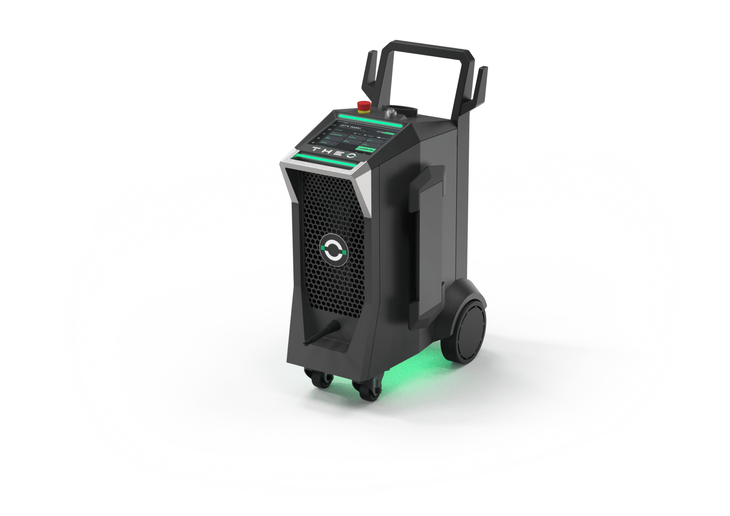
Figure 1: TM Series cleaning machine — product view.
3.3.2 Machine — Front Panel #
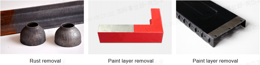
Figure 2: TM Series machine — front panel.
| Nein. | Beschreibung |
|---|---|
| 1 | Emergency-stop button |
| 2 | HMI (touchscreen) display |
| 3 | Fibre output connector |
| 4 | Key switch |
3.3.3 Machine — Rear Panel #
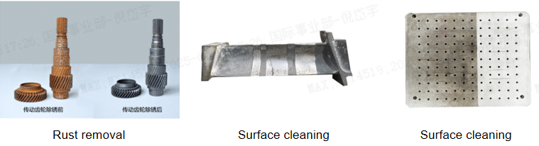
Figure 3: TM Series machine — rear panel.
| Nein. | Beschreibung |
|---|---|
| 1 | Cleaning torch holder |
| 2 | Main ON / OFF switch |
| 3 | Power-cord interface (IEC) |
| 4 | Protective earth (GND) stud |
| 5 | Ethernet interface (RJ-45) |
| 6 | External control interface |
| 7 | Safety interlock interface |
| 8 | Gas inlet |
3.3.4 Cleaning Torch #
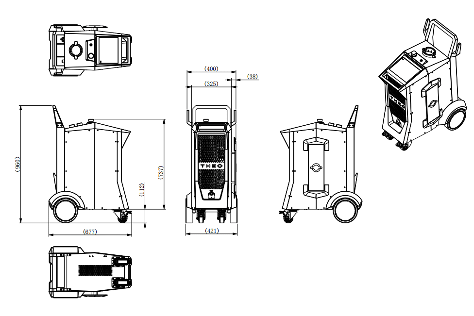
Figure 4: TM Series cleaning torch — side view.
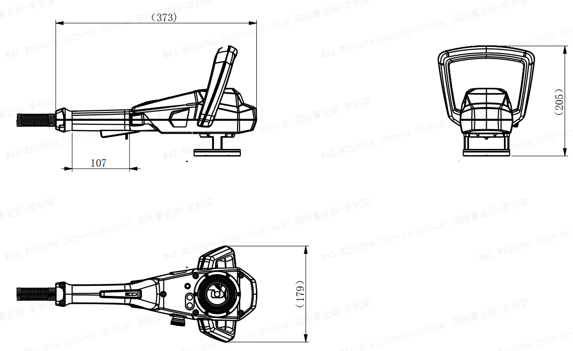
Figure 5: TM Series cleaning torch — detail view.
| Nein. | Beschreibung |
|---|---|
| 1 | Laser output aperture |
| 2 | Distance / IR temperature sensor |
| 3 | Emergency-stop button |
| 4 | ON / OFF button |
| 5 | Operator hand-grip |
| 6 | HMI display |
| 7 | Screen-control button |
| 8 | Laser-enable button (two-stage trigger) |
3.4 Indicator Lights #
Indicator lights on the cleaning torch communicate machine state. Refer to §6 HMI Reference for the full alarm table.
3.5 Connections #
The cleaning machine provides the following connections on the rear panel: AC power input, protective earth stud, Ethernet (RJ-45), external control interface, safety interlock interface, and process-gas inlet.
3.6 Accessories #
3.6.1 Field Lenses #
Three interchangeable field lenses are supplied with the system. The field lens determines the working distance, scan area, and energy density at the workpiece. The target scan area for the TM Series is 100 × 30 mm; final per-lens scan-area values will be confirmed by optical test report.
| Lens | Focal length | Approx. working distance | Approx. scan area at workpiece | Best for |
|---|---|---|---|---|
| F160 | 160 mm | TBD — pending optical test | TBD — pending optical test | Localised, high-energy-density cleaning — fine details, weld preparation |
| F254 | 254 mm | TBD — pending optical test | TBD — pending optical test | Balanced — default lens for most cleaning operations |
| F330 | 330 mm | TBD — pending optical test | TBD — pending optical test | Broad-area cleaning at longer reach — large parts, mould restoration |
When the operator changes the field lens, the Focal Distance value on the HMI Setting interface (§6.4) must be updated to the focal length of the installed lens: enter 160, 254, or 330 (in millimetres) to match the F160, F254, or F330 lens.
4 Commissioning #


|
GEFAHR
Gefahr durch Stromschlag The input voltage of the cleaning system can be deadly. All cables, connectors, and machine housings should be classified as hazardous. Incorrect wiring can cause personal injury or machine damage.
|
|
|
WARNUNG
Gefahr durch unsachgemäße Installation Der Betrieb einer unvollständig montierten Maschine kann zu schweren Verletzungen führen.
|
|
|
HINWEIS
Attach laser warning and laser information signs
|
4.1 Unpacking #

|
WARNUNG
Verletzungsgefahr durch schwere Lasten Das Heben und Transportieren schwerer Lasten kann zu Rückenverletzungen führen.
|

|
ACHTUNG
Gefahr von Sachschäden The machine may be damaged by lifting it out of the packaging by the cable-hose assembly or by the fibre cable.
|
- Überprüfen Sie die Verpackung nach Erhalt der Ware sorgfältig auf äußere Anzeichen von Transportschäden.
- Sollte die Lieferung Transportschäden aufweisen, überprüfen Sie bitte den Inhalt auf mögliche Beschädigungen und benachrichtigen Sie Maxphotonics.
- Öffnen Sie den Karton oben.
- Lesen Sie die Bedienungsanleitung.
- Take the cleaning torch and the accessories out of the packaging and ensure that the fibre-optic cable is intact and undamaged.
- Take out the cleaning machine — two persons required.
- Keep the original packaging in case it is needed later for storage or shipment.
- Beachten Sie bei der Entsorgung des Verpackungsmaterials die örtlichen Vorschriften.
4.2 Setting Up the Cleaning System #
|
|
ACHTUNG
Verletzungsgefahr beim Aufbau When setting up the cleaning system, it may not yet be stable.
|

|
ACHTUNG
Stolper- und Sturzgefahr Falsch verlegte Kabel können zu Verletzungen durch Stolpern oder Stürzen führen.
|
Set up the cleaning system in the following sequence:
- Choose a location inside the laser-safe environment (see §2.6.3.1) with sufficient floor space for the machine, the operator, the workpiece, the fume-extraction unit, and clear escape routes.
- Position the machine on a level, dry, non-conductive floor surface. The machine weighs 57 ± 5 kg — two persons are required for lifting.
- Engage the castor brakes on both castors before connecting cables. Verify that the machine cannot roll.
- Place the cleaning torch in the rear-panel torch holder until ready for use. The fibre-optic cable must hang in a relaxed loop — do not coil tighter than the minimum bend radius marked on the cable.
- Position the HMI display so the operator can read it from the working position without leaning into the laser-controlled area.
- Verify that laser warning signs are posted at every access point to the laser-controlled area (see §2.4.3) and that the door interlock circuit is wired to the safety-interlock interface on the rear panel.
4.3 Connecting the Cleaning System #
- Connect the power cable to the power supply matching the regional cord shipped with the machine.
- Connect the door interlock switch to the machine and tighten both screws.
- Connect the process-gas hose to the inlet port on the back of the machine.
- Connect the ground cable to establish a secure connection between the ground nut of the laser housing and plant ground (see §4.4).
- Connect the communication / fiber cable from the cleaning torch to the front-panel torch interface.
4.4 Procedure for Electrostatic Grounding #
It is important to establish a secure connection between the ground nut of the laser housing and the plant ground using the ground cable supplied, in order to avoid possible damage to the laser due to static electricity.
- Connect the ground cable to the ground connection on the cleaning machine.
- Connect the ground cable with plant ground / ground connection.
4.5 Connecting the Process Gas #
The cleaning head uses compressed air as the process gas. Use dry, oil-free compressed air; check the inlet pressure and the regulator operation before commissioning.
- Connect a gas hose with an outside diameter of 6 mm to the gas inlet.
- Process gas is controlled on/off at the cleaning head; no regulator setpoint is required from the machine side. Supply the gas at a pressure compatible with your facility regulator. A recommended pressure range will be published once gas-pressure testing is complete.
- Verify that the regulator is operational and appropriately rated for the gas and pressure in use.
4.6 Connecting Fume Extraction #
|
|
WARNUNG
Operation without fume extraction is prohibited Laser cleaning vaporises the contaminant layer and generates fume hazardous to health.
|
Connect fume extraction as follows. The TM Series does not ship with a fume-extraction unit; select one rated for the substrate (see §2.5.6) and air-flow capacity sufficient to capture the plume at source.
- Position the fume-extraction unit on the same level as the workpiece, within reach of the cleaning torch nozzle.
- Connect the extraction hose to the fume-capture nozzle on the cleaning torch (or to an external capture hood positioned within 100–150 mm of the workpiece surface).
- Connect the discharge side of the extraction unit to a HEPA + activated-carbon filter cartridge. Verify the filter is rated N100 / P3 or better.
- Power the extraction unit on and verify suction at the capture nozzle before pressing the laser trigger.
- Inspect the filter before every shift; replace per the filter manufacturer’s schedule or when the airflow drops below the rated value.
- For unknown substrates, or substrates flagged in §2.5.6 (lead, hex-chromium, cadmium), upgrade respiratory PPE to supplied-air respirator in addition to local exhaust ventilation.
5 Operation #
This chapter will be completed in V0.9 by the Applications team (Marcel Kratzer, Marcel Mack, Harrison Shoup). The full Operation chapter will cover: power-on, field-lens selection (F160 / F254 / F330), guide-beam alignment, focal-distance setup, parameter selection by application (rust / paint / oxide / coating), pattern selection (Wave / Line / Infinity / Circle), first-clean calibration, shutdown procedure.
5.1 Pre-Start Safety Check (Interim) #
Before powering on the TM Series for any operation, verify every item on the following checklist:
- All persons inside the Nominal Hazard Zone wear correctly rated laser safety eyewear (§2.6.1).
- Functional fume extraction is connected, powered, and sized for the substrate (§2.5.6).
- All operators wear respiratory protection per substrate (§2.6.1.2).
- Combustibles have been removed or shielded; fire extinguisher and fire watch are in place (§2.5.5).
- Cleaning torch is held securely and pointed away from persons and reflective surfaces.
- Emergency-stop buttons (machine and torch) are unlatched and accessible.
- Safety key is inserted; key is in the operator’s possession.
- Safety-interlock circuit is closed (door, booth, or guard as required).
- Workpiece is clean of standing solvents or flammable residues.
- Substrate composition is known and assessed against the ablation-plume hazard table (§2.5.6).
6 HMI Reference #
The TM Series HMI provides five interfaces: Home, Parameter, Status, Setting, and Machine Information.
6.1 Home Interface #
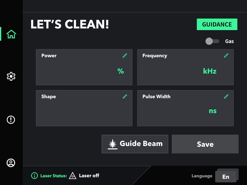
Figure 6: HMI Home interface.
| Nein. | Control | Beschreibung |
|---|---|---|
| 1 | Power | Laser power, 0–100 % adjustable. |
| 2 | Frequency | Pulse repetition frequency, 165–8 000 kHz adjustable. |
| 3 | Shape | Pattern selection: Wave, Line, Infinity, or Circle. |
| 4 | Pulse Width | Laser pulse width, 10–500 ns adjustable. |
| 5 | Guidance | On-screen guidance to assist parameter selection. |
| 6 | Guide Beam | Red Class 2 aiming beam ON / OFF. |
| 7 | Speichern Sie | Save current parameters. |
| 8 | Laser Status | Visual indication of laser ON / OFF state. |
| 9 | Language | Interface language switch. |
| 10 | Gas | Gas On/Off |
6.2 Parameter Interface #
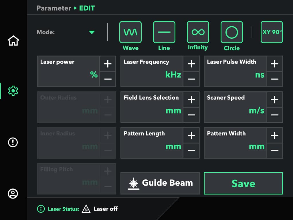
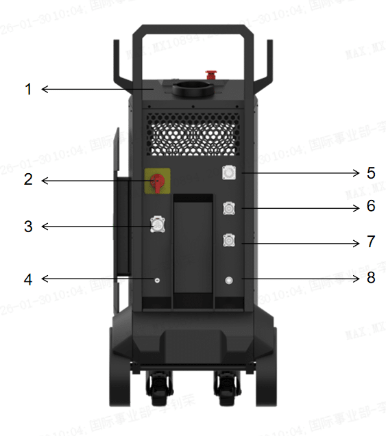
Figure 7: HMI Parameter interface.
| Nein. | Control | Beschreibung |
|---|---|---|
| 1 | Modus | Mode 0–9. Operator can save 9 parameter sets. |
| 2 | Wave | Wave pattern. |
| 3 | Line | Line pattern. |
| 4 | Infinity | Infinity pattern. |
| 5 | Circle | Circle pattern. |
| 6 | Laserleistung | 0–100 % adjustable. |
| 7 | Laser Frequency | 165–8 000 kHz adjustable. |
| 8 | Laser Pulse Width | 10–500 ns adjustable. |
| 9 | Field-Lens Selection | F160 / F254 / F330. |
| 10 | Scanner Speed | 0–30 mm/s. |
| 11 | Pattern Length | 0–100 mm. |
| 12 | Pattern Width | 0–30 mm. |
| 13 | Outer Radius | Circle pattern: 0–100 mm. |
| 14 | Inner Radius | Circle pattern: 0–100 mm. |
| 15 | Fill Pitch | 0–50; smaller = denser fill. |
| 16 | Speichern Sie | Save to one of 9 modes. |
6.3 Status Interface #
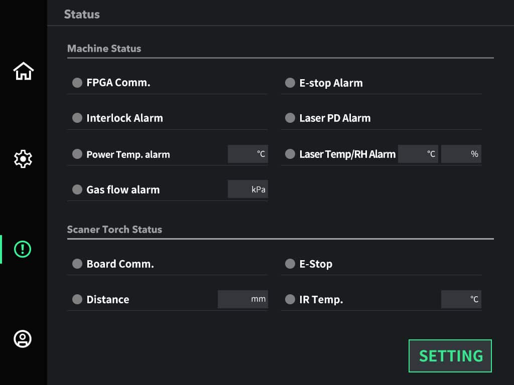
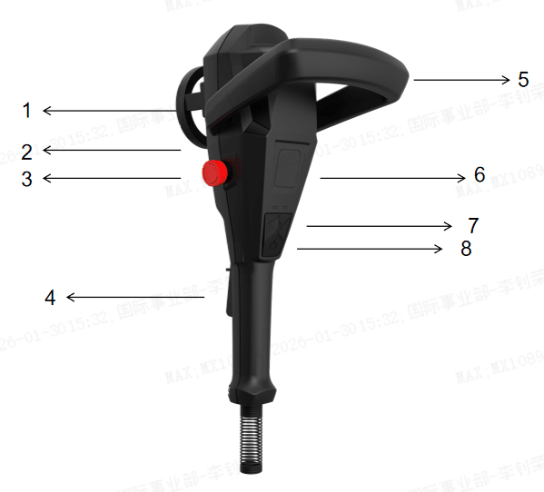
Figure 8: HMI Status interface.
6.4 Setting Interface #
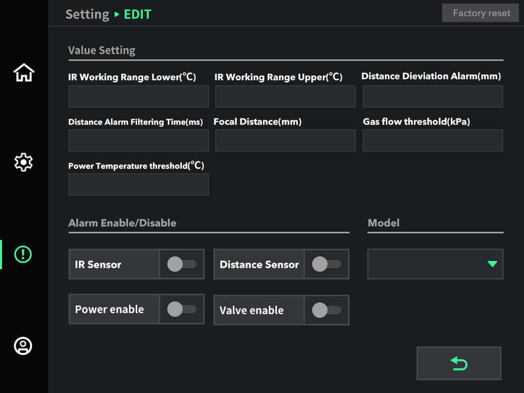
Figure 9: HMI Setting interface.
| Nein. | Status / Alarm | Beschreibung |
|---|---|---|
| 1 | FPGA Comm. | FPGA communication abnormal. |
| 2 | Interlock Alarm | Safety-interlock circuit open. |
| 3 | Power Temp. Alarm | Power-supply over-temperature. |
| 4 | Gas Flow Alarm | Gas flow outside threshold. |
| 5 | E-Stop Alarm | Machine emergency stop activated. |
| 6 | Laser Temp. Alarm | Laser source over-temperature. |
| 7 | Laser PD Alarm | Laser power-detector fault. |
| 8 | Torch Board Comm. | Cleaning-torch control-board communication fault. |
| 9 | Distance Alarm | Distance between torch and workpiece outside threshold. |
| 10 | Torch E-Stop | Cleaning-torch emergency stop activated. |
| 11 | IR Temp. Alarm | IR sensor above or below temperature threshold. |
| 12 | Einstellung | Enter the Setting interface (§6.4). |
| Nein. | Control | Beschreibung |
| 1 | IR Working Range, Lower | IR temperature lower threshold. Default 50 °C. Below this value an alarm is triggered. |
| 2 | IR Working Range, Upper | IR temperature upper threshold. Default 400 °C. Above this value an alarm is triggered. |
| 3 | Distance Deviation Alarm | Alarm if the distance between torch and workpiece changes by more than the threshold during the filter time. Default 5 mm. |
| 4 | Distance Filter Time | Time window for the distance-deviation check. Default 200 ms. |
| 5 | Focal Distance | Enter 160, 254, or 330 (mm) to match the installed field lens (F160 / F254 / F330). |
| 6 | Gas Flow Threshold | Alarm threshold for gas pressure. |
| 7 | Power Temperature Threshold | Alarm threshold for power-supply temperature. |
| 8 | IR Sensor Enable | ON / OFF the IR temperature alarm. |
| 9 | Distance Sensor Enable | ON / OFF the distance alarm. |
| 10 | Gas Valve Enable | ON / OFF the gas-valve alarm. |
| 11 | Power Enable | ON / OFF the power-supply temperature alarm. |
| 12 | Laser Model | Select the laser source model (TM-300G / F). |
6.5 Machine Information Interface #

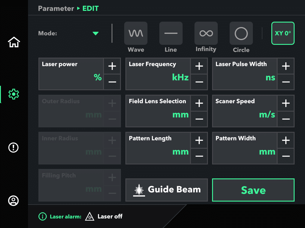
Figure 10: HMI Machine Information interface.
| Nein. | Field | Beschreibung |
|---|---|---|
| 1 | Modell | Machine model name. |
| 2 | Machine PN | Machine part number. |
| 3 | Machine SN | Machine serial number. |
| 4 | HW Version | Hardware version. |
| 5 | MCU Version | Machine MCU firmware version. |
| 6 | FPGA Version | FPGA firmware version. |
| 7 | Torch Version | Cleaning-torch firmware version. |
| 8 | HMI Version | HMI software version. |
Record the values shown on the Machine Information screen at first commissioning. Service requests should reference the machine serial number and the firmware versions listed here.
6.6 Additional HMI Views #
Figure 11: HMI — additional view (parameters in use).
Figure 12: HMI — additional view (status during cleaning).
Figure 13: HMI — additional view (system menu).
7 Cleaning and Exchanging Wear Parts #
7.1 Operator-Authorised Maintenance #
- Visual inspection of the machine, cleaning torch, fibre cable, and power cord before each shift.
- Cleaning of external surfaces with a dry, lint-free cloth.
- Inspection of the protective field lens for contamination, scratches, or damage.
- Inspection of the reflectors inside the cleaning torch.
- Periodic check of the fume-extraction filter (HEPA + activated carbon).
- Periodic check of the emergency-stop buttons, safety key, and safety interlock — verify each before every shift.
|
|
HINWEIS
Operator-restricted maintenance
|
7.2 Field-Lens Care #
The TM Series ships with three field lenses (F160, F254, F330). When replacing or changing a field lens:
- Power the machine off and disconnect from the supply before changing a field lens.
- Wear powder-free nitrile gloves when handling a field lens.
- After installing the new field lens, update the Focal Distance value on the HMI Setting interface (§6.4).
- Use the Class 2 guide beam to verify alignment before resuming Class 4 operation.
|
|
HINWEIS
Field-lens warranty
|
7.3 Cleaning Torch #
The cleaning torch is the operator’s primary point of contact with the machine and accumulates dust, ablation residue, and particulate from the work environment. Follow the inspection and cleaning schedule below.
Daily — before each shift
- Visually inspect the torch housing, the fibre-optic cable, and the laser output aperture for damage, cracks, or contamination.
- Verify the trigger, the screen-control buttons, and the emergency-stop button operate freely.
- Wipe the external housing with a dry, lint-free cloth. Do not use solvents.
- Confirm the protective field lens is clean and free of pits or burn marks.
Weekly
- Remove the protective field lens (power off and disconnect first — see §7.2) and inspect both surfaces under good light. Replace if pitted, scratched, or coated with contamination that cannot be removed with isopropyl alcohol and lens-cleaning wipes.
- Inspect the internal reflectors via the inspection window. If reflectors are dirty, contact service — do not attempt to open the torch housing.
- Verify the fume-extraction nozzle on the torch is clear and unobstructed.
Monatlich
- Inspect the entire fibre-optic cable run for kinks, abrasion, or compression points. Replace any cable showing visible damage.
- Verify the torch hand-grip and the trigger linkage are securely mounted.
- Log the inspection in the employer’s laser-safety log.
When to contact service
- The protective field lens shows pitting or burn marks that return after cleaning.
- Laser output power drops below the rated value for a given parameter set.
- The torch generates abnormal noise or heat during operation.
- Any internal optical component is loose, dirty, or visibly damaged.
8 Help with Faults #
If problems occur during operation, first check whether the operating instructions are strictly followed, then refer to the common faults below for troubleshooting.
| Symptom | Probable cause | Action |
|---|---|---|
| No power indication on the machine at startup; smoke from driver board | Power not connected, or polarity reversed | Disconnect power immediately. Check the connection. If smoke was observed, do not power on — contact Service (see §14). |
| Galvanometer motor humming and overheating after startup | Field lens loose or contaminated; galvanometer mirror loose | Power off. Inspect the field lens and reflectors. If a mirror is loose, contact Service (see §14) — do not attempt to re-seat. |
| Persistent red indicator and clicking noise after startup | Limit-protection activated; input signal amplitude too high | Verify the input control signal is within specification. If normal, contact Service (see §14). |
| Cleaning pattern is rendered as a straight line | One galvanometer axis is not active | Power off. Contact Service — operator-side repair is not permitted. |
| Cleaning pattern shows wavy lines or jitter | Poor protective earth; strong nearby EMI source | Verify the GND stud is correctly connected to facility ground. Check for nearby high-current welding, RF, or induction sources within 5 m; relocate or shield if possible. |
| Square cleaning pattern renders as a diamond | Optical-path misalignment | Power off. Contact Service. Operator-side adjustment is not permitted. |
| Cleaning range does not match expected coverage | Position-signal scale factor incorrect; wrong field lens selected on HMI | Verify the Focal Distance value on the Setting interface matches the installed field lens. |
| Reduced laser power or no laser output | Damaged field-lens coating or broken lens; fibre damage | Power off. Inspect the field lens. If lens is undamaged, contact Service (see §14). |
Service contact
Web: https://theo.inc/support
Email: support@theo.inc
EU phone: +49 (0) 8105 7303890
USA phone: +1 (508) 299 5639
9 Transport and Storage #
|
|
ACHTUNG
Risk of damage during transport Improper transport can damage the cleaning system, the cleaning torch, and the fibre-optic cable.
|
9.1 Transport Procedure #
Prepare the TM Series for transport in the following sequence.
- Power off the cleaning system and disconnect from the mains supply.
- Remove the safety key and store it separately from the machine.
- Disconnect the process-gas hose, the fume-extraction hose, the door interlock, the ground cable, and the Ethernet cable. Cap any exposed connectors.
- Disconnect the cleaning torch from the front-panel interface. Coil the fibre-optic cable in loops no tighter than its minimum bend radius (typically 150 mm; see the cable label).
- Place the cleaning torch in a protective case or in the cleaning-torch holder on the rear panel.
- Release the castor brakes only for the act of moving the machine over short, flat distances. For longer transport, re-engage the castor brakes and lift onto a pallet or into the original packaging.
- For shipping, repack in the original wooden crate with foam pads and shock indicators. Verify the crate is fitted with handling pictograms (this side up, fragile, do not stack).
- Two persons are required for lifting (machine 57 ± 5 kg).
9.2 Storage Conditions #
- Temperature: −10 °C to +60 °C (+14 °F to +140 °F).
- Relative humidity: ≤ 80 %, non-condensing.
- Atmosphere: dry, non-corrosive, indoor.
- Do not stack other equipment on top of the cleaning machine in storage.
- Store the safety key separately from the machine to prevent unauthorised operation.
- After long-term storage (> 6 months), inspect the field lens, the fibre-optic cable, and the protective hoods before returning to service.
10 Disposal #
Dispose of the TM Series in accordance with the regulation applicable in the country of operation:
| Region | Disposal route |
|---|---|
| European Union | WEEE Directive 2012/19/EU — return to distributor or authorised WEEE collection point. The product carries the crossed-out wheeled-bin symbol. |
| Vereinigtes Königreich | Waste Electrical and Electronic Equipment Regulations 2013 — return to authorised UK collection scheme. |
| Vereinigte Staaten | Check state-level e-waste programme. |
| Kanada | Provincial e-waste programmes (Recycle My Electronics / EPRA). |
| Australien | NTCRS does not cover industrial equipment; contact your THEO distributor for take-back. |
| Brasilien | Lei 12.305/2010 (Política Nacional de Resíduos Sólidos) — return to distributor. |
11 Declaration of Conformity #
The TM Series bears the CE marking on the rating plate located on the rear panel of the machine. The EU Declaration of Conformity (DoC) is issued by the manufacturer and maintained by the EU Authorized Representative (see Legal Notice). Copies of the DoC can be obtained by contacting emea@maxphotonics.com or downloaded from https://theo.inc/compliance/.
The TM Series has been declared compliant with the applicable essential requirements of the European directives and regulations listed below, demonstrated by application of the harmonised standards referenced in §2.7.
- Machinery Directive 2006/42/EC (Machinery Regulation (EU) 2023/1230 from 20 January 2027).
- EMC Directive 2014/30/EU — harmonised standards EN IEC 61000-6-2:2019 (immunity) and EN IEC 61000-6-4:2019 (emissions, Class A).
- Low Voltage Directive 2014/35/EU — harmonised standard EN 62368-1:2014+A11:2017.
- RoHS Directive 2011/65/EU as amended by Directive (EU) 2015/863 (RoHS 3).
- REACH Regulation (EC) No 1907/2006.
- Laser-product safety: EN 60825-1:2014+A11:2021.
- Laser processing machines — safety: ISO 11553-1:2020 and EN ISO 11553-2 (hand-held laser processing).
- Machinery safety: ISO 12100:2010, EN 60204-1:2018.
- Instruction handbooks for machinery: EN ISO 20607.
EMC Class A warning (EU)
WARNING — This is a Class A product. In a residential environment this product may cause radio interference, in which case the user may be required to take adequate measures. This equipment is not intended for use in residential environments and may not provide adequate protection to radio reception in such environments.
11.1 United States — FCC, FDA, and California Proposition 65 #
FCC compliance
This device complies with Part 15 of the FCC Rules. Operation is subject to the following two conditions: (1) this device may not cause harmful interference, and (2) this device must accept any interference received, including interference that may cause undesired operation.
FDA / CDRH compliance
This product complies with 21 CFR 1040.10 and 1040.11 except for deviations pursuant to Laser Notice No. 56, dated May 8, 2019. FDA accession number: 2620746-000. The manufacturer’s certification label is affixed to the device.
California Proposition 65 warning
|
|
WARNUNG
California Proposition 65 This product and laser-cleaning operations using it can expose you to chemicals including welding and cleaning fumes (containing hexavalent chromium, nickel, manganese, cadmium) and lead, which are known to the State of California to cause cancer and birth defects or other reproductive harm.
|
11.2 Canada — ICES, Health Canada, Quebec #
ICES compliance
ICES certification pending. ISED Canada ICES classification (ICES-001 ISM vs. ICES-003 ITE) will be determined and the corresponding certificate obtained before sale into Canada. Per the responsible engineer, ICES-001 / EN 55011 (ISM) is not applicable to this product; ICES-003 (ITE) applicability is under review.
Certification ICES en attente. La classification ICES d’ISDE Canada (ICES-001 ou ICES-003) sera déterminée avant la vente au Canada.
Health Canada Radiation Emitting Devices Act
This product complies with the Canadian Radiation Emitting Devices Act and Regulations (Class 4 laser products under Schedule II Part III).
Quebec — French-language notice
Pour les ventes au Québec, conformément à la Charte de la langue française (Loi 96), une version française du présent manuel d’opérateur est disponible à https://theo.inc/manuals/tm-series/fr.
11.3 Australia — WHS, Booth, NHZ #
Australian Work Health and Safety regulations impose specific operating restrictions on handheld Class 4 laser equipment. Operators in Australia must read and apply this section in addition to the general safety requirements in Chapter 2 before placing the TM Series into operation.
|
|
WARNUNG
Australian operating restrictions Australian WHS guidance imposes specific operating restrictions on handheld Class 4 laser cleaning.
|
State-level requirements: Class 4 laser equipment must be registered in some Australian states / territories (notably WA and NSW). Confirm registration obligations with the relevant WorkSafe authority before commissioning. The employer is responsible for appointing a laser safety officer (see §2.4.2).
Australian distributor and service contact: see §14 Contact and Support.
Applicable Australian standards
- AS/NZS IEC 60825.1:2014 — Safety of laser products.
- AS/NZS IEC 60825.14:2022 — User's guide for laser products.
- AS/NZS 1337.4:2011 — Personal eye protection: filters for laser radiation.
- AS/NZS 3000:2018 — Electrical installations (the Wiring Rules).
- Weld Australia Safety Alert WASA-2023-02 — Handheld laser welding (applied as best-practice guidance for handheld laser cleaning).
11.4 Latin America (LATAM) #
Brasilien
Para venda no Brasil, este produto cumpre os requisitos do Código de Defesa do Consumidor (Lei 8.078/1990). Uma versão em língua portuguesa deste manual é obrigatória nos termos do Artigo 31 do CDC e está disponível em https://theo.inc/manuals/tm-series/pt-br.
INMETRO certification: industrial laser-processing equipment in Brazil may fall under the INMETRO compulsory certification regime. Confirm the certification status of the TM Series with your Brazilian distributor before installation.
Spanish-speaking LATAM
Para los mercados de habla hispana en Latinoamérica, una versión en español de este manual está disponible en https://theo.inc/manuals/tm-series/es. Cada país tiene su propio régimen de certificación (NOM en México, IRAM en Argentina, INN en Chile); consulte con su distribuidor THEO local para los requisitos específicos.
12 Technical Data #
12.1 Dimensions #
Figure 14: TM Series cleaning machine dimensional drawing.
| Dimension | Machine | Cleaning torch |
|---|---|---|
| Width × Depth × Height (mm) | 960 × 677 × 477 | 373 × 179 × 205 |
| Weight (kg) | 57 ± 5 (≈ 126 lb) | ≤ 2 (≈ 4.4 lb) |
12.2 Cleaning System — General Parameters #
| Parameter | TM-300G (Gaussian) | TM-300F (Flat-top) | Einheit |
|---|---|---|---|
| Nominal output power | ≤300 | 305 ± 3 | W |
| Beam profile | Gaussian (single-mode) | Flat-top (multi-mode) | - |
| Laser wavelength | 1060–1070 | 1060–1070 | nm |
| Mode of operation | Pulsed | Pulsed | - |
| Repetition frequency | 1–8 000 | 1–4 000 | kHz |
| Full-power frequency range | 165–8 000 | 20–4 000 | kHz |
| Pulse width | 10–500 | 20–500 | ns |
| Pulse energy (peak) | Max. 1.8 (@ 500 ns, 165 kHz) | ≤ 15 | mJ |
| Fibre cable length | 5 | 5 | m |
| Power stability (24 h) | ± 2 | ± 2 | % |
| Beam quality M² | ≤ 1.6 | 10–14 | - |
| Laser beam diameter at output | 4–6 | 4–6 | mm |
| Red guide beam (Class 2) | 200–1 000 | 200–1 000 | µW |
| Fibre core diameter | 30 | 100 | µm |
| Nominal Ocular Hazard Distance (NOHD) | TBD | TBD | m |
| IP rating | Pending — future revision | Pending — future revision | - |
| Rated input current | 12 | 12 | A |
| Recommended upstream fuse | Pending — future revision | Pending — future revision | A |
| EMC class (EN 55011) | Class A, Group 2 | Class A, Group 2 | - |
| Cooling method | Air-cooled | Air-cooled | - |
| Operating temperature | 0–40 (+32–+104 °F) | 0–40 (+32–+104 °F) | °C |
| Lagertemperatur | −10 to +60 (+14 to +140 °F) | −10 to +60 (+14 to +140 °F) | °C |
| Input voltage | 100–240 | 100–240 | V |
| Input frequency | 50 / 60 | 50 / 60 | Hz |
Pulse-energy values are quoted as peak per-pulse energy. The average power, the repetition frequency, and the pulse energy are linked by P_avg = E_pulse × f_rep; only two of the three can be set independently. Refer to the application notes on https://theo.inc/support for the recommended operating envelope per substrate.
12.3 Cleaning Torch — Optical Properties #
| Parameter | Wert | Einheit |
|---|---|---|
| Aperture | 10 | mm |
| Laser wavelength (process) | 1064 ± 5 | nm |
| Standard clean area | 100 × 30 | mm |
| Scan speed | Up to 30 | mm/s |
| Air flow control | ON / OFF | - |
| Cooling method | Air-cooled | - |
13 Warranty #
The TM Series is covered by the THEO Global Warranty Policy for handheld laser tools. The full and authoritative warranty text is published at:
https://theo.inc/warranty
This chapter is a summary of the policy in effect on the date of issue of this manual. In the event of any discrepancy between this summary and the online policy, the online policy at https://theo.inc/warranty in effect at the time of purchase shall prevail.
13.1 Warranty at a Glance #
| Coverage | Period | Notes |
|---|---|---|
| TM Series cleaning machine + cleaning torch + laser source + QCS fibre | 2 years (registered) / 1 year (not registered) | Registration must be completed within 60 days of purchase. |
| Laser safety goggles, helmets, and face shields (if purchased separately) | 1 Jahr | No registration needed. |
| Laser-safety enclosures, partition walls, and curtains (if purchased) | 1 Jahr | Manufacturing defects only. No registration needed. |
| Consumables — field lenses, fume-extraction filters, protective windows | Not covered | Wear items replaced during normal use. |
Warranty start: from the invoice date issued by your authorised dealer. If proof of purchase is not available, the manufacturing date applies.
If something breaks
- Contact your authorised THEO dealer first — they are your contractual partner.
- If unresolved, escalate to THEO directly via the Online Service Form at https://theo.inc/support.
13.2 Registration and Extended Warranty #
To receive the full 2-year warranty, complete product registration at https://theo.inc/registration within 60 days of purchase. Registration requires:
- Scanning the QR code on the machine.
- Completing the registration form and signing the required waivers.
- Completing the THEO Academy laser-safety course (see §2.8).
Upon successful completion, customers receive a permanent activation confirmation. Products not registered within 60 days receive a 1-year warranty only.
An optional extended-protection program, THEO Care, is available during registration. THEO Care plans extend the warranty period and include limited accident protection for the QCS (fibre-optic cable). See https://theo.inc/warranty for current plans and pricing.
13.3 What Is Covered #
THEO warrants the TM Series cleaning machine, the cleaning torch, the laser source, and the QCS (fibre-optic cable that delivers the laser beam from the machine to the torch) against defects in materials and workmanship under normal use, when operated and maintained in accordance with this manual.
The QCS is covered when failure is caused by a manufacturing defect or by a machine malfunction. Damage from running over, kinking, crushing, or stepping on the QCS is NOT covered (see §13.4).
13.4 What Is NOT Covered #
1. Mishandling or misuse
- Dropping the cleaning torch.
- Bending, kinking, or crushing the fibre-optic cable.
- Running over the fibre with a forklift, pallet jack, cart, or vehicle.
- Pulling or stretching the fibre beyond its minimum bend radius.
- Stepping on or pinching the fibre cable.
- Impact damage from collisions or falls.
2. Improper operating conditions
- Operating without proper cooling or with insufficient airflow.
- Operating outside the parameters in §12 Technical Data.
- Operating in environments with excessive dust, humidity, or temperature extremes.
- Failure to maintain ventilation and fume extraction as specified in this manual.
3. Improper storage or transportation
- Storing the unit in extreme temperatures or high humidity.
- Failing to properly secure the fibre during transport.
- Exposure to corrosive chemicals, solvents, or contaminants.
- Damage during shipping due to inadequate packaging.
4. Unauthorised modifications or repairs
- Opening or tampering with sealed components.
- Using non-genuine THEO replacement parts.
- Repairs attempted by uncertified personnel.
5. Consumables and included parts
Wear items including field lenses, protective windows, nozzles, tips, fume-extraction filters, and connection cables / pipes / carrying case supplied with the machine.
6. External factors
- Power surges, lightning strikes, or electrical anomalies.
- Fire, flood, earthquake, or other natural disasters.
- Theft, vandalism, or intentional damage.
- Normal wear and cosmetic damage that does not affect functionality.
13.5 Warranty Service Process #
Step 1 — Contact your authorised dealer
Your first point of contact for all warranty claims is the authorised THEO dealer or distributor from whom you purchased the product. The dealer provides first-line technical support and troubleshooting, local warranty service and repairs, and spare parts and consumables.
Step 2 — THEO Customer Service (escalation)
If you are unable to resolve your warranty claim with your dealer, contact THEO directly via the Online Service Form at https://theo.inc/support. See §14 for regional contact details.
Proof of purchase required
- Original invoice or receipt from an authorised THEO dealer showing purchase date and product serial number.
- Completed product registration (for 2-year warranty claims).
- Product serial number matching THEO’s records.
Authorised dealer requirement
This warranty applies only to products purchased from THEO-authorised dealers and distributors. Products purchased from unauthorised resellers, gray-market sources, or secondary markets are NOT covered, regardless of product condition or registration status. THEO maintains a list of authorised partners at https://theo.inc/partners.
13.6 Out-of-Warranty Repair #
For out-of-warranty repairs, parts and labour are billed to the customer at THEO’s prevailing regional labour rate. Shipping and customs are handled directly by the customer. Current pricing is published at https://theo.inc/warranty.
13.7 Statutory Limitations and Mandatory Rights #
Business-to-business sales only
THEO products are designed and sold exclusively for professional and commercial use. This warranty applies only to products purchased by business entities for use in the course of their trade or profession.
Limitation of liability
TO THE MAXIMUM EXTENT PERMITTED BY APPLICABLE LAW, THEO’S TOTAL LIABILITY ARISING OUT OF OR RELATED TO THIS WARRANTY SHALL NOT EXCEED THE ORIGINAL PURCHASE PRICE PAID FOR THE PRODUCT. THIS LIMITATION DOES NOT APPLY TO DAMAGES THAT CANNOT BE EXCLUDED UNDER APPLICABLE LAW, INCLUDING LIABILITY FOR DEATH OR PERSONAL INJURY CAUSED BY THEO’S NEGLIGENCE OR DEFECTIVE PRODUCTS UNDER THE EU PRODUCT LIABILITY DIRECTIVE (85/374/EEC) OR EQUIVALENT NATIONAL LEGISLATION.
Mandatory rights
Brazilian consumers retain all rights under the Consumer Protection Code (Lei 8.078/1990). Quebec consumers retain all rights under the Consumer Protection Act, R.S.Q. c. P-40.1. EU consumers retain all rights under Directive (EU) 2019/771 on the sale of goods. United States customers retain all rights under applicable state consumer-protection law and the Magnuson-Moss Warranty Act (15 U.S.C. § 2301 et seq.). Australian customers retain all rights under the Australian Consumer Law (Schedule 2 to the Competition and Consumer Act 2010), which cannot be excluded.
Governing law and jurisdiction
USA & Canada: Commonwealth of Massachusetts, USA — courts of Massachusetts.
Europe: Federal Republic of Germany — courts of Munich.
Australia, Japan, Latin America, and all other regions: Hong Kong SAR — courts of Hong Kong SAR.
Policy updates
THEO reserves the right to update this warranty policy. The terms in effect at the date of original purchase apply to that purchase for the duration of the warranty period. The current policy is available at https://theo.inc/warranty.
Refer to https://theo.inc/warranty for the complete and current Legal Terms & Conditions.
14 Contact and Support #
Customer Service — North America
THEO Laser Inc.
1900 West Park Dr., Suite #150, Westborough, MA 01581, USA
Phone: +1 (508) 299 5639
Service: https://theo.inc/support
Customer Service — Europe
THEO Laser Europe c/o MAXPHOTONICS GmbH
Dornierstraße 11, 82205 Gilching, Germany
Phone: +49 (0) 8105 7303890
Service: https://theo.inc/support
Customer Service — Australia
3/14 Robbins Circuit, Williamstown North, VIC 3016, Australia
Service: https://theo.inc/support
Customer Service — Japan / Latin America
Contact local distributor.
Service: https://theo.inc/support
Customer Service — Manufacturer (China)
Maxphotonics Co., Ltd.
MaxPhotonics Industrial Park, Shenzhen, China
Phone: +86 400-900-9588
Web: https://www.maxphotonics.com
Online
Service portal: https://theo.inc/support
Email: support@theo.inc
Appendix A — About THEO and Maxphotonics #
About THEO Laser #
THEO Laser is a brand of Maxphotonics dedicated to handheld laser tools that transform metalwork — welding, cleaning, cutting. Our mission is to put advanced laser capabilities in the hands of professionals at every skill level.
About Maxphotonics #
Founded in 2004, Maxphotonics is a global leader in fibre-laser manufacturing. Maxphotonics designs and manufactures continuous-wave, pulsed, and ultrafast fibre lasers, optical components, and turnkey laser solutions for the automotive, aerospace, electronics, and industrial-processing markets. ISO 9001:2015 certified.
Appendix B — Glossary #
| Term | Definition |
|---|---|
| Ablation | Removal of a surface layer by laser-induced vaporisation. The process by which the TM Series removes contamination. |
| Ablation plume | The vapour, particulate, and gaseous cloud generated above the workpiece during laser cleaning. Composition depends on the substrate (see §2.5.6). |
| AR (Authorized Representative) | The EU-based legal entity designated by a non-EU manufacturer to act on its behalf under EU machinery and product-safety legislation. |
| ATEX | EU regulation regime for equipment intended for use in explosive atmospheres. The TM Series is NOT ATEX-rated. |
| CDC | Código de Defesa do Consumidor — Brazilian Consumer Protection Code (Lei 8.078/1990). |
| CDRH | Center for Devices and Radiological Health (US FDA). Issues 21 CFR 1040.10 laser-product performance standards. |
| Class 2 laser | Low-power visible laser product where the eye’s blink reflex generally provides adequate protection (IEC 60825-1). |
| Class 4 laser | Laser product capable of causing eye and skin damage from direct or diffuse exposure (IEC 60825-1). |
| Cleaning torch | The handheld piece of the TM Series containing galvanometer scanning optics, the laser output aperture, and the operator controls. |
| DoC | Declaration of Conformity. EU manufacturer's statement that a product complies with the applicable directives. |
| EMC | Electromagnetic compatibility — both the emission of and immunity to electromagnetic interference. |
| E-stop | Emergency-stop switch. Hardware push-button that immediately removes power from the laser source. |
| Field lens | F-theta focusing lens at the output of the cleaning torch. Three lenses are supplied (F160 / F254 / F330), corresponding to focal lengths in millimetres. |
| FPGA | Field-programmable gate array — real-time control logic in the cleaning torch. |
| Galvanometer | Electromechanical scanner that moves a mirror through small angles to steer the laser beam across the cleaning pattern. |
| Guide beam | Visible red Class 2 aiming laser used to indicate where the Class 4 process beam will land. |
| HMI | Human-machine interface — the touchscreen on the front of the cleaning machine. |
| LEV | Local exhaust ventilation — air handling that captures contaminants at the source. |
| LSO | Laser Safety Officer. The designated individual responsible for laser-safety supervision under ANSI Z136.1 / EN 60825-1. |
| Maxphotonics | The manufacturer of the TM Series (Maxphotonics Co., Ltd., Shenzhen, China). THEO Laser is a brand of Maxphotonics GmbH. |
| NHZ | Nominal Hazard Zone — the area within which laser-product exposure exceeds the Maximum Permissible Exposure (MPE). |
| NOHD | Nominal Ocular Hazard Distance — the distance from the laser source beyond which direct viewing is no longer hazardous to the eye. |
| OD | Optical density — the attenuation factor of laser safety eyewear at a given wavelength. Higher OD = more attenuation. |
| P3 / N100 | Respirator filter classifications (EU EN 143 / US NIOSH). The highest particulate-filter class; required for hazardous fumes such as hexavalent chromium or lead. |
| PELV | Protected Extra Low Voltage (IEC 61140) — an electrical-isolation class for low-voltage circuits. |
| PPE | Personal protective equipment. |
| QCS | Quick Connect System — the fibre-optic cable that delivers the laser beam from the cleaning machine to the cleaning torch. |
| REACH | EU Regulation (EC) No 1907/2006 on the registration, evaluation, authorisation, and restriction of chemicals. |
| RMA | Return Material Authorisation. A number issued by THEO that authorises the return of a product for service or warranty repair. |
| RoHS | EU Directive 2011/65/EU on the restriction of hazardous substances in electrical and electronic equipment. |
| Substrate | The workpiece material being cleaned. The substrate composition determines the fume hazard and the required engineering controls (see §2.5.6). |
| Theo | THEO's online training platform (academy.theo.inc) providing laser-safety and operating courses. Access is unlocked via the QR code on the machine (see §2.8). |
| TM-300G | Gaussian-beam-profile variant of the TM Series, 300 W class. Single-mode delivery, 30 µm fibre core, M² ≤ 1.6. |
| TM-300F | Flat-top-beam-profile variant of the TM Series, 300 W class. Multi-mode delivery, 100 µm fibre core, M² 10–14. |
| WEEE | EU Directive 2012/19/EU on Waste Electrical and Electronic Equipment. The TM Series carries the crossed-out wheeled-bin symbol. |
| WHS | Work Health and Safety — Australian / New Zealand occupational-safety regulatory framework. Imposes specific operating restrictions on handheld Class 4 laser equipment (see §11.3). |
