Operating Manual
Dual Wire Feeder Expansion Kit
For THEO MA1 Series Handheld Laser Welders
Manufactured by
AK Industry GmbH
Messerschmittstr. 2 · 86825 Bad Wörishofen · Germany
Document version 1.0 · English · Translation of the original German operating manual
Imprint #
メーカー番号#
|
会社概要 |
AK Industry GmbH |
|
住所 |
Messerschmittstr. 2, 86825 Bad Wörishofen, Germany |
|
Telephone |
+49 8247 / 381 949 0 |
|
電子メール |
info@ak-industry.de |
|
ウェブサイト |
www.ak-industry.de |
Document Version #
|
バージョン |
日付 |
変更 |
|---|---|---|
|
0.1 |
2025-11-01 |
Initial release (German) |
|
1.0 |
2026-04-28 |
English translation of the original German manual |
Scope of Application #
This operating manual applies to the accessory kit for dual-wire welding on THEO MA1 handheld laser welders.
|
シリーズ |
Model |
|---|---|
|
THEO |
MA1-45 |
|
MA1-65 |
|
|
MA1-Ultra |
About this Operating Manual #
The German version is the original operating manual. All other language versions are translations of the original.
Always store this operating manual within easy reach so you can refer to it whenever you need information about the product.
Only pass the product on to other persons together with this operating manual.
Read and observe the safety and warning notices in this operating manual.
安全#
|
注意 |
|
レーザー溶接システムにおける負傷および損傷のリスク Failure to read and follow the safety information and operating instructions can result in personal injury and damage to the laser welding system. 将来参照できるよう、同封の書類はすべて保管しておいてください。 Observe the safety notices and follow the operating instructions to ensure safe operation. |
Safety Regulations #
Structure of Warning Notices #
Warning notices in this manual follow the standard format below:
- Signal word — DANGER, WARNING, CAUTION or NOTICE.
- Type and source of hazard.
- Consequences if the hazard is ignored.
- Measures to avoid the hazard.
Symbols and Signal Words #
The following signal words are used to classify hazards:
|
Signal word |
意味 |
|---|---|
|
危険 |
Indicates an imminently hazardous situation that, if not avoided, will result in death or serious injury. |
|
警告 |
Indicates a hazardous situation that, if not avoided, could result in death or serious injury. |
|
注意 |
Indicates a potentially hazardous situation that, if not avoided, may result in minor or moderate injury. |
|
お知らせ |
Indicates a situation that, if not avoided, may result in property damage or malfunction. |
Warning Signs #
The following pictograms are safety notices used in this operating manual. They serve personal safety and must be strictly observed.
|
記号 |
説明 |
|---|---|
|
|
General warning sign |
|
|
Warning — laser radiation |
|
|
Warning — electrical voltage |
|
|
Warning — obstacles on the floor (trip hazard) |
|
|
Warning — hand injuries |
|
|
Warning — hot surface |
|
|
Warning — gas cylinders |
|
|
Warning — inadequate laser-protective enclosure |


Mandatory Signs #
The following pictograms are mandatory-action notices used in this operating manual. They serve personal safety and must be strictly observed.
|
記号 |
説明 |
|---|---|
|
|
General mandatory sign |
|
|
Read the operating manual! |
|
|
レーザー用安全ゴーグルを着用してください! |
|
|
Wear a laser protective mask (helmet)! |
|
|
Wear laser protective gloves! |
|
|
Wear a laser protective apron! |
|
|
Wear safety footwear! |
|
|
耳栓などを着用してください! |
|
|
Connect to ground before use! |


Intended Use #
The Dual Wire Feeder Kit may only be used in conjunction with the THEO MA1 series for welding metals. Any other use voids the manufacturer’s liability and warranty claims.
Application range:
- The laser is intended exclusively for commercial use in industrial environments (indoor); not for domestic use.
- Welding tasks on heavier sheet metal up to 10 mm material thickness.
Reasonably Foreseeable Misuse #
The following uses are explicitly forbidden because they are dangerous:
- Operating the laser without the safety devices specified by the manufacturer.
- Operation by children, or by persons who are unable to operate the machine correctly and safely; using the machine in unventilated rooms.
- Tampering with, bypassing, or disabling existing safety devices.
- Disassembling the machine.
- Deliberate manipulation of the operating elements; any modification, alteration, or extension of the machine or its electrical system not authorised by the manufacturer.
- Disturbance of the electronics through strong magnets or other strongly emitting objects carried near the machine.
- Using a damaged machine or damaged machine parts, especially the laser head or safety devices.
- Exceeding the operating parameters specified by the manufacturer.
- Pointing the laser gun at persons. The laser must only be aimed at the work surface.
- Operating the machine without personal protective equipment.
- Exposing the machine to severe and rapid temperature fluctuations or to humid or wet environments.
- Using the laser in an explosion-hazard area or with combustible liquids/gases (the system has NO Ex-protection).
General Safety Information #
Handheld laser welding systems are Class 4 laser products as they emit invisible, infrared laser radiation at a wavelength of 1,080 nm.
Because the laser head emits more than 1 W on average, this high-intensity light can cause direct or indirect damage to eyes and skin. In particular, exposure to this laser beam can cause irreversible damage to the retina or cornea.
It is mandatory to wear certified 1,080 nm near-infrared laser safety goggles before operating any handheld laser welding application. The use of a suitable laser-protective helmet is also recommended.
Safe Use #
|
警告 |
|
Hazard from laser radiation Exposure to the laser beam can cause irreversible damage to the retina or cornea. Avoid looking directly at the gun outlet, and ensure that suitable laser safety goggles are worn while the laser is in use to prevent eye injuries. Do not open the handheld laser welding system. There are no user-serviceable parts inside. Train personnel regularly and inform them of the risks associated with this technology. Safety and responsibility always rest with the operator. Inform anyone who occasionally enters the laser area to confirm in advance whether the laser is in operation. Any operation or adjustment performed outside the guidelines in this operating manual may damage the system or impair its function. Stray laser radiation can cause damage to skin and other tissue. Inspect the protective glass regularly for contamination. When in doubt, replace the protective glass (see “Replacing the protective glass”). |
Operating Environment Requirements #
Handheld laser welding equipment is typically used:
- In approved laser cells
- Below 2,000 metres above sea level
- Under overvoltage category II
- Under pollution degree 2
Provide a separate room or area, and/or use suitable laser-protective walls or curtains together with relevant laser-safety components (warning light, safety-coded switch, signal) to establish an adequate safety zone that meets the local laser-protection requirements.
Use a suitable laser-protective enclosure and inform persons in the surrounding area.
Mark the entrances to the laser area with a laser-protection symbol indicating that a Class 4 laser is in use.
Gas: the laser welding system requires either clean, dry, oil-free compressed air or, alternatively, nitrogen.
Workpieces: ensure a stable, secure position and prevent any unintended sliding or change of position.
Extraction: laser processing produces fumes and dust that are harmful to the human body. Provide adequate fume extraction.
Set up the system in a safe, sheltered, and dry location. For further information, refer to the technical data.
Optical Safety Measures #
- Do not look directly into the laser-output aperture of the handheld system or into the pilot laser.
- Hold the handheld system and its associated optical output devices (handpiece) below eye level and always away from the operator.
- Ensure that all personal protective equipment (PPE) is suitable for the system’s power output and wavelength range.
- Do not use the handheld system in dark environments.
- Switch off the handheld system and disconnect it from the power supply before installing or cleaning the protective glass.
- The laser power is transmitted through a protective glass. Ensure the protective glass is clean and of high quality. Any dust on the optical components can damage both the protective glass and the laser.
- When clearing a fault, the laser must be switched off and secured against being switched back on. Switch the laser back on only after the fault has been cleared.
- Operate the system strictly in accordance with the instructions in this operating manual. Otherwise, the protective devices and the performance of the system may be impaired, and the manufacturer cannot be held responsible.
Electrical Operating Guidelines #
- When operating the system, ensure proper grounding of the power supply and the specified mains voltage.
- Before using the system, make sure that the connected power supply is also bonded to protective earth.
- To minimise the risk of fire, only replace fuses with fuses of the same type and rating. Do not use any other fuses or materials for this purpose.
- Make sure that the AC input voltage is within the normal mains-voltage range and that wiring is correct. Improper wiring can cause personal injury or damage to the system.
- Connect the system to a suitable outlet and inspect cables for damage.
- Operators must not perform repairs on parts, components, or assemblies other than the consumables of the welding gun. All repair work must be performed by qualified service personnel.
- It is strictly forbidden to disassemble and reassemble the handheld system without authorisation, as this can lead to electric shock, burns, or damage to the affected components.
- Unauthorised disassembly of the product voids the warranty.
Cooling and Temperature #
The laser unit is air-cooled. Operating at higher temperatures accelerates ageing, raises the threshold current, and reduces slope efficiency.
Before starting the laser, make sure the ambient temperature and humidity are within the recommended specification.
Operating the system at high temperatures can accelerate ageing, raise the current threshold, and reduce sensitivity and conversion efficiency. If the system overheats, contact service.
If the laser temperature is too high, the system triggers an alarm and stops emitting laser radiation.
Service Life #
The manufacturer recommends the following measures to extend service life:
- Ensure adequate ventilation in the work area and place the machine in a dry, cool, clean environment. Avoid high temperatures, humidity, and risk of water ingress.
- When operating the system, make sure that no foreign objects block the air inlet on the side of the laser, and keep the area within 1 metre clear of contaminants to ensure uninterrupted airflow.
- When operating the system, make sure that no foreign objects block the air outlet on the side of the laser, and keep the area within 1 metre clear of contaminants to ensure uninterrupted airflow.
- Prevent foreign objects (including liquids) from entering the laser from above. This can damage the system and may cause injury.
掃除#
- Do not kink the torch hose package; the optical fibre inside can break.
- Regularly remove dust and dirt from the system.
- Clean the handpiece with dry cloths, not with compressed air.
- Contact AK Industry service if you detect any damage.
- For safe operation, the machine should be inspected regularly by AK Industry service.
- Inspect protective glasses and replace them as soon as signs of wear appear (see “Replacing the protective glass”).
Fume Extraction #
Install fume-extraction systems to remove hazardous fumes, vapours, particles, and residues from the work area.
Residual Risks #
Despite proper design and compliance with all relevant safety standards, certain hazards cannot be completely excluded when using the Dual Wire Feeder accessory kit. The following residual risks remain even with intended use and must be observed by the operator.
Mechanical Residual Risks #
Crushing and draw-in hazard at the wire feeder
When the two welding wires are fed automatically, there is a risk that fingers or gloves may be drawn into or crushed by moving parts.
Operator protective measures:
- Keep hands away from the wire feeder.
- Do not reach into the system during operation.
- Carry out cleaning and adjustment work only when the system is stopped.
Thermal Residual Risks #
Hot welding nozzle / torch components
After welding, the nozzle, contact tips, and surrounding components can become very hot. There is a risk of burns.
Operator protective measures:
- Touch the nozzle only after a sufficient cooling period.
- Wear heat-resistant protective gloves.
- Do not place the torch on combustible surfaces.
Welding sparks and molten spatter
Dual-wire welding produces increased sparks and spatter, which can cause burns, damage to clothing, or fires.
Operator protective measures:
- Use personal protective equipment (PPE), e.g. flame-retardant clothing and a laser welding helmet.
- Remove combustible materials from the work area.
- Use suitable shielding and spark curtains.
Trip and Tip-Over Hazards #
Hose package / cables
The increased weight and length of the hose package can create trip hazards.
Operator protective measures:
- Route the hose package in an orderly manner.
- Cordon off or mark trip-hazard areas.
- Perform regular visual inspections for damage.
Electrical Residual Risks #
Even when all components comply with applicable standards, wear or damage can lead to electrical hazards (e.g. insulation faults, malfunctions).
Protective measures:
- Regular inspection by qualified personnel.
- Do not use damaged cables or connectors.
- Take the system out of service immediately if any abnormality is detected.
Other Possible Residual Risks #
- Smoke and gas emissions: insufficient extraction can cause respiratory irritation.
- Noise exposure: dual-wire processes can produce elevated noise levels.
- Operator error: improper settings can cause malfunctions and consequential risks.
Standards and Directives #
In accordance with EU and national standards and requirements, lasers must be classified based on their output power and wavelength. All laser products of the THEO MA1 Series fall under Class 4 according to EN 60825-1.
Electromagnetic compatibility — immunity #
- EN IEC 61000-6-4:2019
- EN IEC 61000-6-2:2019
Power-supply safety #
- EN 62368-1:2014 + A11:2017
Machinery and EMC #
- Machinery Regulation (EU) 2023/1230 (formerly Machinery Directive 2006/42/EC)
- EMC Directive 2014/30/EU
レーザーの安全性#
- ISO 12100:2010
- ISO 11553:2017
- EN 60204-1:2018
機能安全#
- EN 60825-1:2014 + A11:2021
- CDRH 21 CFR 1040.10
Dual Wire Feeder Kit #
Scope of Delivery #
The Dual Wire Feeder Kit is supplied with the following components:
|
Qty |
説明 |
|---|---|
|
1 |
Welding-gun holder for dual wire |
|
1 |
Dual-wire control unit |
|
1 |
Power supply for Dual Wire Feeder Kit |
|
1 |
Power cord for Dual Wire Feeder Kit (EU) |
|
1 |
Aluminium holder for dual wire (incl. 2 × M3 × 10 mm cap screws each) |
|
4 |
Hose-package holders for dual wire (set of 4) |
|
1 |
Liner holder at gun for dual wire (incl. 2 × M2 × 12 mm cap screws) |
|
2 |
Dual-wire feed nozzle, 1.2 mm |
|
2 |
Dual-wire feed nozzle, 1.6 mm |
|
2 |
AS-12D nozzle |
|
2 |
AS-16D nozzle |
|
1 |
Dual-wire feed assembly |
|
1 |
Nozzle adapter for MA1 dual wire |
|
1 |
Dual stainless-steel liner, 1.6 mm, 3 m, for MA1 |
Order reference: A103553 AK — Dual Wire Feeder Kit for THEO handheld laser welders.
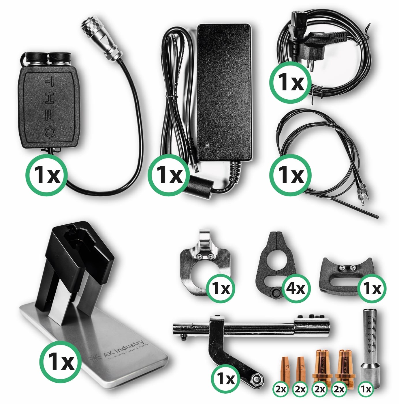
Figure 1 — Dual Wire Feeder Kit, scope of delivery.
Technical Data #
|
説明 |
Value |
|---|---|
|
Compatible devices |
THEO MA1-45 / MA1-65 / MA1-Ultra |
|
Synchronisation control |
Electronic mirroring of the master feeder parameters |
|
Control-unit supply |
24 V DC (via the kit power supply) |
|
Maximum feed speed |
12 mm/s |
|
Compatible wire materials |
Stainless steel (VA), unalloyed steel (SG), and AlMg |
|
Maximum wire diameter |
1.6 mm |
|
Minimum wire diameter |
0.8 mm |
|
Operating ambient temperature |
+5 °C to +45 °C |
|
Protection class (IP) |
IP54 |
Installation Instructions — Dual Wire Feeder Kit on the MA1 Series #
General Installation Notes #
|
注意 |
|
Risk of injury and property damage The Dual Wire Feeder Kit must only be installed by trained, qualified personnel. Before starting any work, fully disconnect the laser welding system from the mains and shut off the gas supply. Wait until all moving parts have come to a complete stop and there is no further hazard from coast-down. |
Required Documents and Tools #
- THEO MA1 laser welder operating manual
- This Dual Wire Feeder Kit operating manual
- Hex (Allen) keys, at minimum M1.5, M2, M3, and M5
- Screwdrivers as required for the screws used
- Personal protective equipment per the “Laser-protection measures” chapter (at minimum: laser safety goggles)
|
お知らせ |
|
Verify completeness before installation Make sure all components of the Dual Wire Feeder Kit listed under “Scope of Delivery” are complete and undamaged before starting installation. |
Preparation of the Welding Gun and Wire Feed #
Prepare the Workplace #
- De-energise the system and secure it against being switched back on.
- Position the welding gun, hose package, and wire feeder so that all components are easily accessible.
- Clean the work area and remove any loose parts.
Remove Existing Nozzle Adapter and Wire Feed #
- Loosen the existing nozzle adapter on the welding gun.
- Carefully remove the wire feed currently mounted on the gun.
- Set aside all removed parts and protect them from damage if they are to be reused later.
|
お知らせ |
|
Avoid kinking the hose package Avoid kinking or sharply bending the hose package. The optical fibre inside can break under excessive load and damage the system. |
Preparing the Second Wire Feeder #
Mount/Position the Wire Feeder #
- Install or set up the second wire feeder at a suitable location near the first wire feeder.
- Ensure that the planned routing of the wire feed and the dual liner is free of tension.
Insert and Pre-Feed the Wire #
- Load the welding wire into the second wire feeder.
- Make sure the correct feed rollers are fitted for the wire diameter used (e.g. 1.2 mm or 1.6 mm).
- Feed the wire through the rollers and pre-feed it sufficiently so that it can later be inserted into the dual-wire feed without difficulty.

Figure 2 — Loading wire into the second wire feeder.
|
お知らせ |
|
Set roller pressure correctly Correct contact pressure of the feed rollers is important to avoid wire deformation and to ensure consistent feed. |
Electrical Connection of the Dual Wire Feeder Kit #
Connect Both Wire Feeders to the Dual-Wire Control Unit #
- Connect the electrical leads of both wire feeders to the dedicated sockets on the dual-wire control unit.
- Ensure correct assignment of connections.

Figure 3 — Wire feeders connected to the dual-wire control unit.
Connect the Control Unit to the Laser Source #
- Connect the dual-wire control unit to the laser source at the “Feeder” interface.
- Insert plug-in connectors fully and ensure they latch securely.
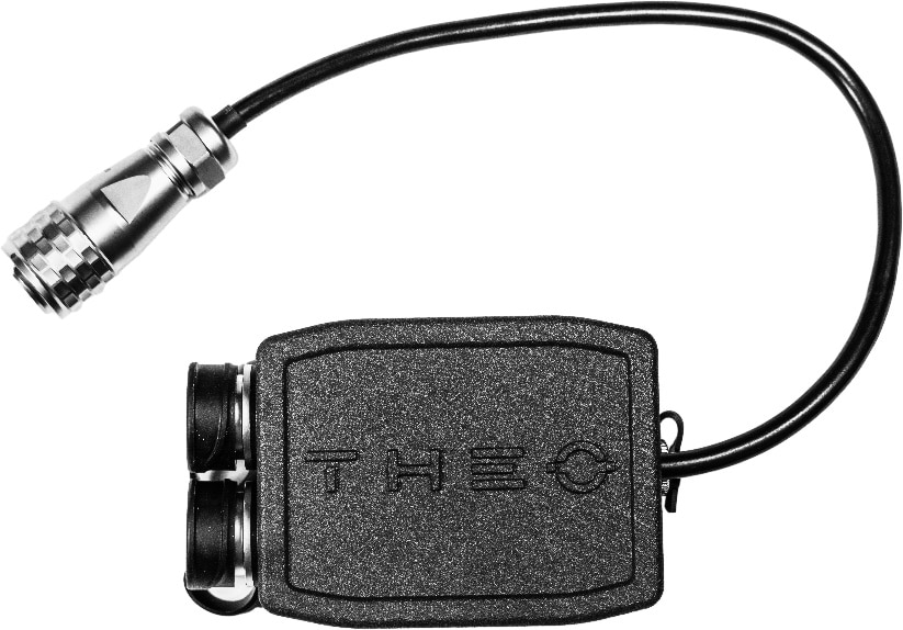
Figure 4 — Control unit connected to the laser source at the “Feeder” interface.
Connect the Power Supply #
- Connect the power supply included with the kit to the dual-wire control unit.
- Plug the EU power cord into the power supply, but only connect it to the mains after all assembly work is complete.
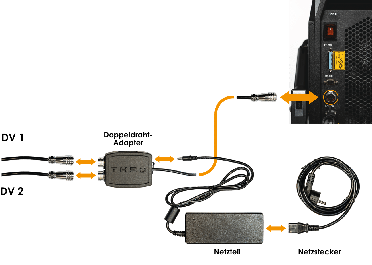
Figure 5 — Power supply and EU mains cord.
|
警告 |
|
Risk of electric shock All electrical connections must be made with the system de-energised. Damaged cables or connectors must be replaced immediately and must not be used. |
Connecting the Wire Feed #
Connect the Wire Feed #
- Connect the supplied dual-wire feed assembly to both wire feeders via the quick couplings.
- Ensure the quick couplings are firmly seated; unintentional disengagement must be prevented.
Pre-Feed the Wires Automatically #
- Use the “automatic pre-feed” function on the wire feeders to advance both wires until they protrude approximately 10 cm from the dual liner.
- Check that both wires emerge from the wire feed parallel to each other and without binding.
|
お知らせ |
|
Avoid wire binding during pre-feed Make sure the wires do not bind against each other or rub on edges during pre-feed. Otherwise, feed problems may occur during operation. |
Mounting the Dual-Wire Feed on the Liner and on the Gun #
Mount the Dual-Wire Feed on the Dual Liner #
- Fit the dual-wire feed with the matching dual-wire feed nozzle (corresponding to the wire diameter, e.g. 1.2 mm or 1.6 mm) onto the dual stainless-steel liner.
- Position the dual liner so that a straight wire run is ensured.
- Secure the dual-wire feed to the liner using the existing set screws.
Mount on the Hand Torch #
- Position the prepared dual-wire feed on the hand torch.
- Fasten the dual-wire feed to the hand torch with two M3 hex-socket cap screws (Allen screws).
- Tighten the screws evenly to avoid distortion.
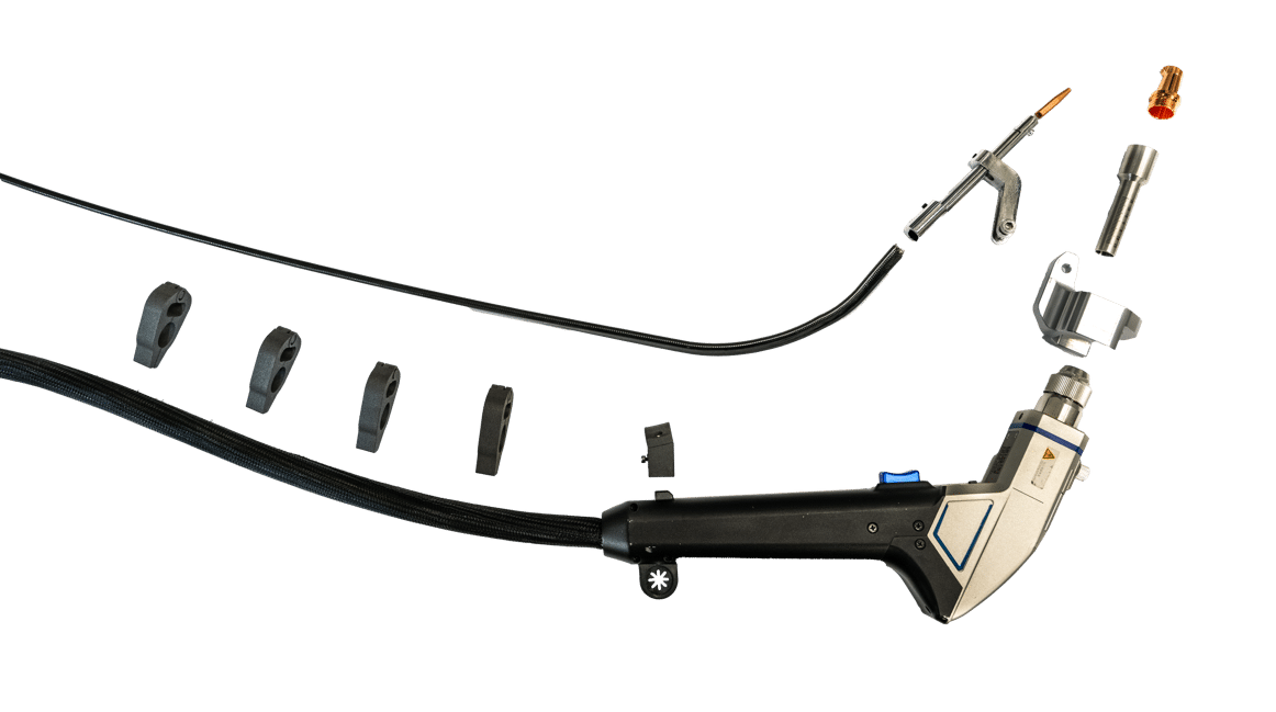
Figure 6 — Mounting the dual-wire feed on the hand torch.
|
お知らせ |
|
Do not over-tighten Over-tightened set screws or M3 screws can damage the dual liner and cause wire-feed problems. |
Mounting the Nozzle and the Nozzle Adapter #
Select the Correct AS Nozzle #
- Select the AS nozzle (AS-12D or AS-16D) according to the wire diameter in use.
- Use only the nozzle sizes approved in the technical specification.
Screw the Nozzle into the Nozzle Adapter #
- Screw the selected AS nozzle into the nozzle adapter for MA1 dual wire.
- Make sure the nozzle is fully screwed in and securely tightened.
Insert the Nozzle Adapter into the Gun #
- Insert the assembled nozzle adapter, including the nozzle, into the welding gun.
- Use the existing knurled screw to fix it in place until the nozzle adapter sits without play.
- Set the focus position on the gun to −3.
Final Assembly of the Liner and Adjustment of the Nozzles #
Insert the Liner into the Dual-Wire Feed #
- Insert the liner into the dual-wire feed until it seats correctly against the dual-wire feed nozzle.
- Secure the liner with the set screw on the dual-wire feed.
Set the Nozzle Spacing #
- Make sure the dual-wire feed nozzle ends approximately 2 mm before the dual AS nozzle.
- Only a small air gap should remain between the two nozzles.
- This gap ensures that both wires pass cleanly and without friction through the dual nozzle.
Adjust the M5 Fixing Screw #
- Tighten the M5 fixing screw only once both wires are guided into the nozzle with light pre-tension.
- Verify by activating the feed function that the wires move evenly and without jerking.
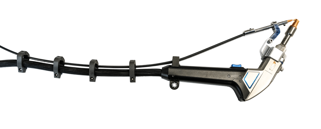
Figure 7 — Final assembly and nozzle adjustment.
|
お知らせ |
|
Maintain the correct gap and pre-tension An air gap that is too large, or incorrect wire pre-tension, can cause uneven penetration or spatter during welding. |
Pilot-Laser Alignment and Functional Test #
Switch On the Laser #
- After all mechanical assembly work is complete, switch the system on per the “Commissioning” chapter.
- Make sure all laser-safety measures are active and that laser safety goggles are worn.
Align the Pilot Laser #
- Switch on the pilot laser.
- By rotating the nozzle adapter, align the pilot laser so that its light spot is centred between the two wires.
- Then lock the position of the nozzle adapter.
Apply Settings #
- Process parameters are set as in the single-wire system.
- The control board mirrors the settings to the second wire feed so that both wires operate synchronously.
Run a Trial Weld #
- Perform a short trial weld on suitable test plates.
- Check that both wires melt evenly and that the bead matches the expected result.
- Fine-tune wire feed, focus position, or laser power as required.
Installation Checklist #
Before commissioning, verify and check off all of the following items:
- System de-energised, gas supply shut off, laser-safety measures active.
- All components of the Dual Wire Feeder Kit complete and undamaged (scope of delivery verified).
- Original nozzle adapter and single-wire feed properly removed.
- Second wire feeder mechanically mounted or safely set up.
- Correct feed rollers for the wire diameter in use (e.g. 1.2 mm / 1.6 mm) fitted in both wire feeders.
- Wire correctly loaded in both wire feeders, contact pressure set.
- Dual-wire control unit electrically connected to both wire feeders.
- Dual-wire control unit connected to the laser source at the “Feeder” interface.
- Power supply correctly connected to the dual-wire control unit.
- Dual-wire feed connected to both wire feeders (quick couplings securely latched).
- Both wires automatically pre-fed; protrude approximately 15 cm from the dual liner.
- Dual-wire feed with dual-wire feed nozzle correctly fastened on the dual liner (set screws tightened, but not over-tightened).
- Dual-wire feed mounted firmly on the hand torch with two M3 screws.
- Correct AS nozzle (e.g. AS-12D or AS-16D, matching wire diameter) selected and screwed into the nozzle adapter.
- Nozzle adapter for MA1 dual wire inserted into the gun and fixed with the knurled screw.
- Focus position on the gun set to −3.
- Dual liner correctly inserted into the dual-wire feed and secured with the set screw.
- Spacing: dual-wire feed nozzle ends approximately 2 mm before the dual AS nozzle (small air gap present).
- M5 fixing screw tightened so that both wires are guided with light pre-tension.
- Wire feed actuated as a test: both wires run evenly and without jerking.
- Pilot laser switched on and aligned so that the light spot is centred between the two wires.
- Trial welds produced; bead appearance and burn-off behaviour of both wires verified.
- Wire feed, focus position, or laser power fine-tuned as required.
Fault Diagnosis #
If a fault occurs, refer to the table below. If the fault cannot be cleared, contact AK Industry service.
|
Symptom |
Possible cause |
Remedy |
|---|---|---|
|
One wire does not feed |
Dual liner kinked / roller contaminated |
Inspect liner; clean rollers |
|
Wires run asymmetrically |
Different roller pressure |
Equalise contact pressure on both feeders |
|
Pilot laser not centred |
Nozzle adapter rotated |
Repeat alignment |
|
Spatter / uneven penetration |
Wires binding; nozzle gap incorrect |
Verify 2 mm gap; re-align wires |
|
Feed jerking |
Dual liner damaged |
Replace liner |
|
Unsteady weld bead |
Focus incorrect |
Check focus position on the handpiece (−3) |
Disposal #
The Dual Wire Feeder Kit and all of its electrical components are subject to the WEEE Directive 2012/19/EU.
- Electronic assemblies, the control unit, the power supply, and the wire feeders must not be disposed of with household waste.
- Return them via municipal collection points or directly through AK Industry GmbH.
- Metallic parts of the wire-guide assembly can be sent to recycling.
- Dispose of consumables (e.g. nozzles, liners) separately.
