会社概要#
正式な代理店/輸入業者およびサービス番号#
|
Maxphotonics |
|
|---|---|
|
住所 |
Dornierstr.11 |
|
電話番号 |
+49 (0)8105 7303890 |
|
電子メール |
|
|
ウェブサイト |
theo |
メーカー番号#
|
深センMaxPhotonics |
|
|---|---|
|
住所 |
MaxPhotonics 団地 |
|
電話番号 |
+86 400-900-9588 |
|
電子メール |
|
バージョン番号#
|
バージョン |
日付 |
変更 |
|---|---|---|
|
2.0 |
2025年6月6日 |
初回リリース |
適用範囲#
本取扱説明書は、一般に「ハンドヘルド型レーザー溶接システム」と呼ばれる、THEO シリーズの機器に適用されます。
|
シリーズ |
種類 |
|---|---|
|
MA1 |
MA1-35 |
|
MA1-45 |
|
|
MA1-65 |
|
|
MA1 ULTRA |
この取扱説明書について#
- この取扱説明書のドイツ語版が原本です。その他の言語版はすべて、この原本を翻訳したものです。
- 本機に関する情報が必要な場合にすぐに参照できるよう、この取扱説明書は常に手の届く場所に保管してください。
- 本機を他の方に譲渡する際は、必ずこの取扱説明書を同梱してください。
- 本取扱説明書に記載されている安全上の注意事項および警告をよくお読みの上、それに従ってください。
安全#
注意#


レーザー溶接システムにおける負傷および損傷のリスク
安全上の注意事項や取扱説明書の内容を十分に理解していないと、人身事故やレーザー溶接システムの損傷につながる恐れがあります。
- 将来参照できるよう、同封の書類はすべて保管しておいてください。
- 安全な操作を行うため、安全上の注意事項を遵守し、取扱説明書に従ってください。

補足情報#
安全規則#
補足情報#
警告の構成#
危険#
危険の種類と発生源
危険を無視した場合の結果。
- その危険を防止するための措置。
記号および注意事項の説明#
危険#
致命的な怪我の危険性
この警告は、生命や健康に対する差し迫った危険を示しています。この警告を無視すると、重傷や死亡につながる恐れがあります。
警告#
怪我をするリスクが高い
この注意書きは、健康に重大なリスクをもたらす危険な状況について警告するものです。この警告を無視すると、重傷や死亡につながる恐れがあります。
注意#
怪我の危険性
この注意書きは、健康へのリスクをもたらす可能性のある危険な状況について警告するものです。この警告を無視すると、軽傷を負う恐れがあります。
お知らせ#

本通知では、追加情報を提供しています。
警告ラベル#
以下に示すピクトグラムは、レーザー溶接システムに表示されているもの、および/または取扱説明書で使用されているものです。
これらの警告ラベルは、個人の安全のためのものであり、必ず遵守してください。
|
記号 |
説明 |
|---|---|
|
|
一般的な警告ラベル |
|
|
レーザー光線に関する警告 |
|
|
電圧に関する警告 |
|
|
床上の障害物に関する警告 |
|
|
手の怪我に関する警告 |
|
|
高温の表面に関する警告 |
|
|
ガスボンベに関する警告 |
|
|
レーザー安全エンクロージャーの不備に関する警告 |
|
|
直射光および反射光に関する警告 |
|
|
レーザー光線に関する警告 |
|
|
溶接ヒュームの吸入に関する警告 |


必須の標識#
以下に示すピクトグラムは、レーザー溶接システムに表示されているもの、および/または取扱説明書で使用されているものです。
これらの義務標識は、個人の安全を守るためのものですので、必ず遵守してください。
|
記号 |
説明 |
|---|---|
|
|
一般的な義務表示 |
|
|
取扱説明書に従ってください! |
|
|
レーザー用安全ゴーグルを着用してください! |
|
|
溶接用マスクを着用してください! |
|
|
レーザー用安全手袋を着用してください! |
|
|
レーザー安全エプロンを着用してください! |
|
|
安全靴を履いてください! |
|
|
耳栓などを着用してください! |
|
|
ご使用前に必ずアースしてください! |


使用目的#
レーザー溶接機とワイヤフィーダーで構成されるこのレーザー溶接システムは、鋼、アルミニウム、ステンレス鋼など、さまざまな材料を手動で溶接するための装置です。
適用分野:
- 本レーザーは、産業環境(屋内)における業務用途のみを目的としており、個人での使用は想定されていません。
- MA1シリーズは、溶接およびはんだ付け用途に適しています。
- このレーザーは、金物、建材、キッチン家電、航空宇宙産業、自動車産業などの分野で活用できます。
予見可能な悪用の可能性#
安全上のリスクがあるため、以下の行為は避ける必要があります:
- メーカーが指定した安全装置を装着せずにレーザーを操作すること。
- 子供や、本機を安全かつ正しく操作できない者が本機を使用すること、および換気のない場所での本機の使用。
- 既存の安全装置を改ざん、迂回、または無効化すること。
- 機械の分解。
- 操作部品の意図的な操作、および製造元が規定していない機械や電気系統の改造、変更、拡張。
- 強力な磁石やその他の強い電磁波を放出する物体を携帯することで、電子機器に干渉が生じる。
- 機械またはその部品、特にレーザーヘッドや安全装置が損傷している状態での使用。
- メーカーが定めた動作パラメータを超過している。
- 溶接トーチを人に向けてはいけません。使用中は、レーザーを作業面に向けてください。
- 個人用保護具を着用せずに機械を使用すること。
- 機械を、急激かつ激しい温度変化や、湿気や水気の多い環境にさらすこと。
- 爆発性環境や可燃性液体・ガスの付近でのレーザーの使用(防爆対策なし)。
一般的な安全上の注意事項#
手持ち式のレーザー溶接機は、波長1080 nmの不可視の赤外線レーザー放射を放出するため、レーザー製品のクラス4に分類されます。
溶接ヘッドから放出される高強度の光は、平均1 W以上あり、目や皮膚に直接的または間接的な損傷を与える可能性があります。特に、このレーザー放射にさらされると、網膜や角膜に回復不可能な損傷を引き起こすおそれがあります。
安全な操作を確保するため、ハンドヘルド型レーザー溶接機を使用する前には、1080 nm用の適切な認証を受けた近赤外レーザー用安全ゴーグルを着用することが不可欠です。
補足情報#
安全な使用方法#
警告#


レーザー放射線の危険!
レーザー放射線にさらされると、網膜や角膜に回復不可能な損傷が生じるおそれがあります。
- 目の怪我を防ぐため、レーザーの照射口に直接目を向けないでください。また、レーザーを使用する際は、必ず適切なレーザー用保護ゴーグルを着用してください。
- 本ハンドヘルド型レーザー溶接システムには、ユーザーが取り外しや修理を行うことを想定した部品や修理方法は一切ありませんので、絶対に開けないでください。
- 従業員に対して定期的に研修を行い、この技術に内在する危険性を周知徹底してください。安全な使用と使用に伴う責任は、利用者自身にあります。
- そのエリアにたまにしか立ち入らない人を含め、全員に対し、レーザーが稼働中かどうかを事前に確認するよう指示してください。
- 本取扱説明書の指示に従わない操作や設定を行うと、システムの損傷や故障の原因となる可能性があります。
- 拡散したレーザー放射は、皮膚やその他の組織に損傷を与える可能性があります。このため、安全ガラスとノズルに汚れが付着していないか定期的に確認してください。疑わしい場合は、安全ガラス(「安全ガラスの交換」を参照)とノズル(「ノズルの交換」を参照)を交換してください。
要員要件#
- レーザー溶接システムは、資格を有する担当者のみが操作することができます。
- 有資格者とは、以下の条件を満たす者を指します:
- 操作方法および適用される安全規則について研修を受けています。
- Maxphotonics、THEO それらの認定販売・サービスパートナーが提供するトレーニングコースを無事に修了しました。
- 取扱説明書を読み、その内容を理解しました。
- 組み立て、設置、および使用の際は、現地で適用される法的規制および技術基準を遵守しなければなりません。
- 当該機械の操作を担当または許可されていない者が、機械に近づくことは固く禁じられています。許可されていない者に対しては、作業区域から退去するよう指示しなければなりません。
- 従業員は常に適切な個人用保護具を着用しなければなりません。
- レーザー溶接システムは、精神上または身体上の障害のある方、子供、および高齢者が使用してはなりません。
- レーザー溶接中は、ワークピースの周辺またはその部屋にいるすべての人が、溶接トーチの後方に位置していなければなりません。
レーザー安全責任者#
- クラス3R、3B、または4のレーザー機器を操作する前に、雇用主が必要な技術的専門知識を有していない場合は、雇用主はレーザー安全責任者を任命しなければならない。
- レーザー安全責任者の職務内容は、関連する欧州規格に規定されています。
- レーザー安全責任者は、その職務を遂行するために必要な技術的専門知識を有していなければならない。専門的資格は、研修コースを修了することで証明され、継続的な研修を通じて維持されなければならない。
- レーザー安全責任者は、以下の点において雇用主を支援します:
- リスク評価の実施
- 必要な安全対策の実施
- レーザーの安全な稼働状況を監視する。
- レーザー安全責任者は、職務を遂行するにあたり、労働安全責任者および産業医と連携する。
動作環境の要件#
- 手持ち式のレーザー溶接機は、一般的に次のような用途に使用されます:
- 認定済みのレーザー溶接セルにおいて
- 標高2000メートル未満
- 過電圧カテゴリ II
- 汚染度 2
- 組み立て場所は、安全で、保護されており、乾燥していることを確認してください。詳細については、技術データ(「Technische Daten」を参照)をご覧ください。
- 別の部屋またはエリアを確保するか、あるいは適切なレーザー安全用仕切り壁やカーテン、およびレーザー安全に関連する構成要素(警告灯、コード式安全スイッチ、信号)を用いて、現地の規制に準拠したレーザー安全要件を満たす適切な安全エリアを設けること。
- 適切なレーザー安全エンクロージャーを使用し、作業現場の周囲の人々にその旨を伝えてください。
- レーザーゾーンへのすべての出入口に、クラス4のレーザーが稼働中であることを示すレーザー警告マークを掲示してください。
- ガス:このレーザー溶接システムでは、シールドガスとしてアルゴンが必要です。なお、ステンレス鋼やアルミニウムの溶接には窒素(N2)が使用されます。
- 被加工物:被加工物が確実に固定されていることを確認し、自発的な滑りや位置ずれが生じないようにしてください。
- 排気:レーザー溶接では、人体に有害な煙や粉塵が発生します。適切な排気設備を設けてください。
光学系の安全対策#
- ハンドヘルド型レーザー溶接機のレーザー出力開口部やパイロットレーザーを直視しないでください。
- 手持ち式のレーザー溶接機および関連する光出力装置は、常に目の高さより下に置き、使用者から離して保持してください。
- 個人用保護具(PPE)のすべてが、製品のレーザー安全ラベルに記載されている出力および波長範囲に対応した設計となっていることを確認してください。
- 暗い場所では、手持ち式レーザー溶接機を使用しないでください。
- 安全ガラス、銅製ノズル、およびワイヤフィーダーモジュールの取り付けや修理を行う際は、ハンドヘルド型レーザー溶接機の電源がオフになっていること、および電源供給が遮断されていることを確認してください(「レーザー溶接機の電源を切る」を参照)。
- レーザー光は安全ガラスを通して照射されます。安全ガラスが清潔で、高品質であることを確認してください。ヒーターユニットにほこりが付着していると、安全ガラスやレーザーに損傷を与える恐れがあります。
- 不具合を解消する際は、レーザーの電源を切る必要があります。不具合が解消された後、レーザーの電源を再び入れてください。
- 本取扱説明書に記載されている通りに厳守して本機器をご使用ください。そうしない場合、安全装置や本機器の性能に支障をきたす恐れがあり、その場合、製造元は一切の責任を負いかねます。
補足情報#
NOHD値#
公称眼危険距離(NOHD)とは、レーザービームを直視すると眼の損傷を引き起こすおそれのある危険区域のことです。
NOHD値(「光学特性」参照)で示される限界値を遵守し、適切な個人用保護具(「個人用保護具(PPE)」参照)を着用することが不可欠です。

|
1 |
皮膚および眼に対するレーザーの危険区域 |
2 |
目に対するレーザーの危険区域 |
|
3 |
目の安全距離(NOHD限界値) |
|
|
電気運転規則#
- 本装置を操作する際は、電源が適切に接地されており、正しい電圧が印加されていることを確認してください。
- 本装置を操作する前に、接続された電源も保護接地を介して適切に接地されていることを確認してください。
- 火災の危険を最小限に抑えるため、必要な場合は、同一のタイプおよび定格のヒューズのみを使用してください。この目的のために、他のヒューズや材料を使用しないでください。
- ハンドヘルド型レーザー溶接機の入力交流電圧が、200~240 V ACという通常の単相範囲内にあること、および配線が正しいことを確認してください。配線が間違っていると、人身事故や装置の損傷を引き起こすおそれがあります。
- 本機器を適切な接続端子(機器に応じて16 Aまたは32 A)に接続し、ケーブルに損傷がないか確認してください。
- ユーザーは、溶接トーチの消耗品に関するメンテナンスを除き、いかなる部品、構成部品、またはモジュールについても修理を行ってはなりません。すべての修理は、サービス技術者が行う必要があります。
- ユーザーがハンドヘルド型レーザー溶接機を独自に分解・再組み立てすることは固く禁じられています。感電、火傷、または関連部品の損傷につながる恐れがあるためです。
- 許可なく製品を分解すると、保証が無効となります。
冷却と温度#
耐用年数#
メーカーは、耐用年数を延ばすために以下の手順を推奨しています:
- 作業場所には十分な換気を確保し、機械は乾燥した、涼しく、清潔な環境に設置してください。高温、高湿度、および水による危険を避けてください。
- 本装置を操作する際は、レーザー下部の吸気口が塞がれていないことを確認し、空気の流れが妨げられないよう、半径1メートル以内の範囲を清浄な状態に保ってください。また、上部の排気口が1メートル以上高い位置にあることを確認してください。
- レーザー溶接機の上部から異物(液体を含む)が侵入しないようにしてください。異物が侵入すると、装置が損傷したり、人身事故につながる恐れがあります。
掃除#
レーザー溶接の危険性#
補足情報#
レーザー放射#
- 目に見えない直射光や反射光に誤ってさらされないよう、安全上の指示に従ってください。
- 本システムは、指定されたレーザー管理区域内でのみ使用してください。
健康への悪影響#
レーザーを浴びると、網膜や角膜に深刻な損傷を引き起こす可能性があり、その結果、眼に永続的な障害が生じたり、場合によっては皮膚にも損傷が生じたりする恐れがあります。
補足情報#
眼への損傷#
レーザー溶接機#
溶接作業中は、可視光および不可視の放射線が放出され、作業者に危害を及ぼすおそれがあります。高出力のレーザービームと溶接対象の材料との相互作用により、拡散レーザー放射が発生する可能性があります。
溶接作業では、紫外線や「ブルーライト」を放出するプラズマが発生することがあります。これらの放射は、結膜炎、網膜への光化学的損傷、および日焼けに似た皮膚反応を引き起こす可能性があります。適切な保護措置を講じずに紫外線にさらされた場合、目に不可逆的な損傷を負う恐れがあります。
- メーカーは、レーザー照射エリアにいるすべての者が、反射・拡散したレーザービームや、強いレーザー光、紫外線、熱、火花から目や皮膚を保護するため、レーザー用安全ゴーグルやレーザー溶接用ヘルメットなどの個人用保護具を着用することを推奨しています。
ワイヤフィーダー#
溶接ワイヤの通線や手動での移動を行う際、目の怪我につながる恐れがあります。
- ワイヤーフィーダーのトーチライナーの接続部を直視しないでください。
- トーチライナーの出口を直視しないでください。
- ワイヤ供給ノズルを直視しないでください。
- 顔や目を保護するため、安全ゴーグル、レーザー溶接用ヘルメット、またはレーザー溶接用マスクなどの個人用保護具を着用してください。
皮膚の損傷#
溶接作業中、作業者は赤外線や紫外線による皮膚損傷のリスクにさらされます。これらの放射線は皮膚の火傷を引き起こす可能性があり、皮膚がんのリスクを高めたり、皮膚の早期老化を招いたりする恐れがあります。また、溶接時の火花によっても火傷を負うことがあります。レーザー溶接後、加工された材料は極めて高温のままである場合があります。
- レーザー制御区域内の利用者および第三者は、レーザー用防護服、耐熱手袋、帽子、革製エプロン、その他のレーザーおよび耐熱性のある衣服などの防護服を着用することが推奨されます。
- 袖と襟のボタンは留めておいてください。
- 加工済みの部品を、レーザーがワークピースに照射されるような位置に決して置かないでください。危険を招く恐れがあります。
反射による危険#
ハンドヘルド型レーザー溶接機の出力開口部からは、さまざまな角度で放出される二次レーザービームを生成することができます。主ビームが平らな表面で反射された際に発散ビームを生成するこの現象は、鏡面反射と呼ばれます。
二次レーザービームのエネルギーは一次レーザービームに比べて著しく低いものの、その強度は依然として、目や皮膚、あるいは特定の材料の表面に損傷を与えるのに十分な場合がある。
- 適切な個人用保護具を着用してください:レーザー用安全ゴーグル/レーザー溶接用ヘルメット、レーザー用安全手袋、レーザー用安全エプロン。
- ユーザーおよび第三者は、常に反射の可能性に留意しなければなりません。レーザー設定が不適切であると、反射が増える恐れがあります。
- 作業者および第三者は、常に溶接トーチの後方にいなければなりません。
- 溶接作業中は、反射範囲内に人がいないこと、および可燃物が存在しないことを確認してください。
- 溶接姿勢に適したノズルを使用してください。
- 反射率の高い材料(アルミニウムや銅など)を溶接する際は、レーザービームのエネルギーの一部が溶接対象部位によって反射される可能性があるため、特に注意を払ってください。
- 加工対象の各部品について、予想される反射円錐の範囲を把握し、その範囲内を直視したり、身体のいかなる部分もその範囲内に侵入させたりしないようにしてください。
補足情報#
二次的な放射線被ばくの危険性#
溶接工程では、可視光および不可視光の両方が発生します。高出力レーザービームと溶接対象の材料との相互作用により、紫外線(UV)や、「青色光」を放出するプラズマが発生することがあります。この放射線は、結膜炎、網膜への光化学的損傷、日焼けに似た皮膚反応など、さまざまな健康問題を引き起こす可能性があります。
適切な保護措置を講じずに、こうした目に見えない紫外線にさらされると、目に永久的な損傷を負う危険があります。溶接作業中にたとえ短時間でも紫外線にさらされると、視界のかすみ、灼熱感、過度の涙、目の痛み、刺激感といった症状が現れることがあり、これらはしばしば「目に砂が入ったような感覚」と表現されます。
- 症状が現れた場合は、直ちに医師に相談してください。
爆発の危険性#
ガスボンベは、破損していたり、溶接作業場の近くに置かれていたりすると、爆発の危険があります。
- シールドガスボンベは、衝撃やレーザー溶接の影響を受けて損傷しないような安全な場所に保管してください。
- シールドガスボンベは、熱源、火花、炎から遠ざけてください。
- 遮蔽ガスボンベを直立させた状態で固定し、頑丈なガスボンベホルダーに取り付けてください。
- レギュレーターが正常に動作していること、および使用中の特定のガスと圧力に対して適切な定格であるかを確認してください。
- ガス圧が適切に設定されていることを確認してください。
- ホースや接続部が用途に適しており、最適な状態にあることを確認してください。
火災の危険性#
溶接中に発生する熱や火花により、溶接箇所の周辺にある可燃物が引火したり、爆発したりするおそれがあります。
- 溶接作業中に発生する熱や火花により火災や爆発を引き起こす恐れがあるため、可燃物を溶接作業エリアから遠ざけてください。
- 引火性または可燃性の物質が存在する環境では作業を行わないでください。レーザー溶接は、可燃性物質がない場所でのみ行ってください。
- 可燃性または引火性の物質が含まれている、あるいは含まれていると見られる容器に対して、決して溶接作業を行ってはならない。
- 消火器は、すぐに手が届く場所に置いておき、従業員が正しい使用方法を習得していることを確認してください。
- レーザーは、アルコール、ガソリン、エーテル、その他の溶剤などの揮発性物質に引火するおそれがあります。本装置の設置および操作の際は、必要な安全対策を講じ、溶剤や可燃性物質、可燃性ガスへの曝露を避けてください。
溶接ヒュームの危険性#
溶接ヒュームは、溶接材料、溶加材、シールドガス、塗料、コーティング材、化学反応、および大気汚染物質が混ざり合うことで生じる微細な粒子やガスから構成される場合があります。溶接ヒュームは、肺、心臓、腎臓、および中枢神経系に悪影響を及ぼす可能性があります。
レーザーがプラスチック、金属、複合材料などの被加工材料と相互作用すると、それらが気化して、有毒かつ危険な煙や蒸気の雲が発生することがあります。これらは目に見えないことが多く、深刻な健康リスクをもたらします。 換気が不十分な密閉空間で溶接作業を行うことは極めて危険です。有毒な濃度の煙やガスが急速に蓄積し、意識喪失や窒息を引き起こす恐れがあるからです。溶接中に放出される紫外線は、空気中の酸素や窒素と反応してオゾンや窒素酸化物を生成しますが、これらは高濃度になると致命的となる可能性があります。また、溶接に使用されるシールドガスが空気を置換し、身体への危害や死に至る事態を引き起こすこともあります。
これらのリスクを軽減するには:
- 作業エリアから有害な煙、蒸気、粒子、および有害な残留物を除去するために、排煙システムを設置してください。
- 溶接材料に同梱されている安全データシートおよび警告事項をよく読み、それらに従ってください。
- なお、排気システムに加え、狭い場所やその他の危険な状況では、外気の供給が必要になる場合があることにご留意ください。
- 作業は常に換気の良い場所で行ってください。
- 作業エリア内の有害ガスの濃度を把握するため、定期的に空気の質を監視してください。
- 溶接中は、危険な煙にさらされないよう、頭を煙の発生源から遠ざけてください。
- 狭い場所や、その他必要とされる状況では、呼吸用保護具を使用してください。
レーザーの安全対策#
補足情報#
個人用保護具(PPE)#
レーザーが新規システムに設置される場合でも、既存のシステムに後付けされる場合でも、個人用保護具の適合性を判断する責任は、ユーザーにのみある。
すべての個人用保護具は、装置の出力および波長範囲に適したものでなければならず、十分な保護機能を備えている必要があります。また、溶接工程に伴う二次放射線の危険性についても考慮しなければなりません。
目や皮膚の怪我、および聴覚障害を防ぐため、適用される規制に準拠した衣服および保護具を着用しなければなりません。
服装は実用的(体にフィットしたもの)で、動きを妨げないものでなければなりません。長い髪は必ずヘアネットを着用してください。
個人用保護具は、以下のものから構成されています:
- レーザー安全ゴーグル
- レーザー溶接用ヘルメット
- 聴覚保護
- 安全手袋
- 安全靴
- 長袖・長ズボンの服
補足情報#
レーザー用安全ゴーグルまたはレーザー溶接用ヘルメット#
EN 207:2017 認証を取得したレーザー用安全ゴーグル、またはレーザー出力要件を満たすレーザー溶接用ヘルメットを着用してください。レーザー用安全ゴーグルおよびレーザー溶接用ヘルメットは、当該装置の全波長範囲にわたって保護機能を備えている必要があります。
本製品の操作や取り扱いを行う際は、レーザー用安全ゴーグル、またはレーザー溶接用ヘルメットとフェイスマスクの着用が義務付けられています。
機械のすぐ近くにいる者は、同様の個人用保護具を着用しなければなりません。
レーザー出力:連続波(CW)動作時、最大2000 W
And direct or near indirect exposure (e.g. < 1 m distance)
安全装備の推奨レーザー防護レベル:
- 1070 nm~1075 nm用 OD9+、D LB6 + IR LB8 + M LB9
- 1075 nm~1080 nm用 OD8+、D LB6 + IRM LB8
- 1080 nm~1087 nm用 OD7+、D LB6 + IRM LB7
レーザー溶接用ヘルメット:個人用保護具(PPE)規則(EU)2016/425、EN ISO 16321-1:2022、EN ISO 16321-2:2021、EN 207:2017
材料のレーザー保護レベル:900-1100 D LB5 / LB7 R LB8 CE
観察窓のレーザー保護等級:900-1080 D LB7 IR LB8 CE
推奨事項#
|
記号 |
説明 |
|---|---|
|
|
レーザー溶接用ヘルメットの着用をお勧めします。
|

レーザー用安全手袋#
EN 388:2016+A1 に準拠し、機械的リスクに対する保護機能を備え、かつ EN 12477:2001+A1:2005 に準拠した溶接作業に適した、レーザーおよび耐熱性の安全手袋を着用してください。
安全手袋は、皮膚への被ばく量が許容限度を超えないよう、波長1070 nmのレーザー放射に対する保護機能を備えていなければならない。安全手袋は、溶接および類似の作業における防護服の上から着用する場合、規格EN ISO 11611に準拠したものでなければならない。また、熱および炎からの保護を目的として防護服の上から着用する場合、規格EN ISO 11612に準拠したものでなければならない。
レーザー安全エプロン#
溶接および類似の作業を行う際は、EN ISO 13688:2013+A1:20221 および EN ISO 11611:2015 に準拠した認定済みの防護服を着用してください。
安全・保護装備#
補足情報#
人材育成#
レーザー溶接システムの操作は、適切な指導と訓練を受けた者のみが許可されています。
個人用保護具#
適切なレーザー保護レベルを備えた個人用保護具(PPEを参照)を着用してください。仕様については、技術データをご参照ください。
安全キー#
安全キーがない場合、レーザー溶接装置は電源スイッチで電源を入れることはできますが、レーザーを動作させることはできません。
- 位置 1:レーザー作動中。
- 位置 0:レーザーがオフ。
ドアインターロックスイッチおよびレーザー安全エンクロージャー#
レーザー溶接機は、レーザー溶接セル内、またはインターロック式の安全装置を備えた囲いの中でしか操作してはなりません。予期せぬ侵入があった場合、インターロック(ドア接触スイッチ)により、レーザー溶接システムが自動的に停止します。レーザーは停止します。
オペレーターは、管理対象のレーザー作業エリアへの立ち入りを許可する適切なドアコンタクトスイッチを正しく設置し、その確実な動作を確保する責任を負います。
非常停止スイッチ#
非常停止スイッチを押すと、レーザーは直ちに停止します。コントロールパネルには「非常停止中!」というメッセージが表示されます。
- 非常停止スイッチは押し下げられた状態でロックされたままです。溶接はできなくなりました。
- 非常停止スイッチを回すとロックが解除され、スイッチは元の位置に戻ります。
ブレーキ付きキャスター#
レーザー溶接機とワイヤフィーダーには、安定性を確保するため、ブレーキ付きのキャスターが取り付けられています。
溶接トーチの機能制御#
溶接トーチのレーザー先端が被加工物の表面に接触し、レーザートリガーが作動するまで、溶接プロセスは開始されません。
ワークステーションの機器#
- 使用するワークステーションは、オペレーターが指定します。
- 十分な作業スペース、機能エリア、保管場所、および動線・避難経路を確保すること。
- このレーザー溶接機は、1人で操作できます。
本デバイスの操作部#
- 移動式レーザー溶接機の筐体にあるハンドル。この装置は移動や操作が可能です。
- レーザー溶接機の試運転および調整作業用制御盤
- 被溶接物の溶接用トーチ
補足情報#
レーザー安全エンクロージャー#
IEC 60825-4:2006 に準拠した適切なレーザー安全エンクロージャー内で作業を行ってください:
- レーザー防護ブース/レーザー溶接セル
- レーザー用安全カーテン
- レーザー安全仕切り壁
溶接ヒュームの排気#
作業エリアから有害な煙、蒸気、粒子、および有害な残留物を除去するために、排煙システムを設置してください。
作業手順#
|
|
溶接中は、常に反射領域の後方、かつレーザー反射ゾーンの外側に位置してください。
|
|
|
反射率の高い材料(アルミニウムや銅など)を溶接する際は、多重反射が生じる可能性があるため、注意を払ってください。
|


危険ゾーン#
|
|
溶接作業中、手持ち式レーザー溶接機の正面一帯は、放出されるレーザー放射のため、危険区域と定義されます。 作業エリアのすぐ近くには、当該ユーザーのみが立ち入ることが許可されています。 |

規格および規制#
EUおよび各国の規格や要件に基づき、レーザーは出力と波長に応じて分類されなければなりません。MA1シリーズのすべてのレーザー製品は、EN 60825-1に基づき、クラス4のレーザー製品に分類されています。
電磁両立性に対する耐性#
- EN IEC 61000-6-4:2019
- EN IEC 61000-6-2:2019
電源の安全性#
- EN 62368-1:2014+A11:2017
レーザーの安全性#
- ISO 12100:2010
- ISO 11553-2017
- EN 60204-1:2018
機能安全#
- EN 60825-1:2014+A11:2021
- CDRH 21 CFR 1040.10
Theo #
THEO 、THEO 溶接機の安全な使用方法およびメンテナンスに関する基礎研修をオペレーターに提供するオンライン学習プラットフォームです。
その他のトレーニングコース、機械の設定方法、安全に関する動画については、THEO (theo)をご覧ください。
THEO アカデミーの主な提供内容:
- 装置のセットアップと操作:MA1シリーズのハンドヘルド型レーザー溶接機のセットアップおよび基本的な操作について、順を追って解説した動画チュートリアルです。
- レーザー安全報告書:クラス4レーザーの危険性に関するトレーニング動画および説明書。リスク評価と安全対策に重点を置いています。
- 個人用保護具(PPE):1080 nmの赤外線レーザー用安全ゴーグルおよびその他の必須保護具の正しい使用方法に関する詳細なチュートリアル。
- 安全な作業手順:業界基準への準拠を確保するための、適切な取り扱い方法、定期的なメンテナンス、および安全手順に関するオンライン講座。
オペレーターは、THEO モジュールを自分のペースでオンラインで受講することができます。動画チュートリアルや教材は、初心者から経験豊富なユーザーまでを対象としており、安全な作業慣行と最高のパフォーマンスの実現を促進するよう設計されています。
コースを無事に修了した参加者には、修了証が授与されます。
MA1デバイスのシリアル番号を使用して登録を行うと、追加のリソースにアクセスしたり、マシンソフトウェアのライセンスを取得したりすることができます。登録を行うことで、機能や特徴をすべてご利用いただけるほか、製品サポートも受けられるようになります。
商品説明#
MA1シリーズのレーザーは、クラス4の認定を受けたレーザー製品です。これらのレーザーはダイオードレーザー技術を採用しており、波長範囲は1070 nm~1090 nm、効率は約30%です。
このハンドヘルド型レーザー溶接システムは、レーザー溶接機、溶接トーチ、ワイヤフィーダー、および制御システムで構成されています。
型番の数字は、ハンドヘルド型レーザー溶接機の溶け込み深さを示しています。
例:MA1-35:高合金鋼用 3.5 mm
補足情報#
納品範囲#
|
いいえ。 |
コンポーネント |
説明 |
数量 |
|---|---|---|---|
|
1 |
溶接トーチと電源ケーブル付きの手持ち式レーザー溶接機 |
MA1-35 / MA1-45 / MA1-65 / MA1 ULTRA |
1 |
|
2 |
アースケーブル |
5 m または 10 m |
1 |
|
3 |
レーザー安全ゴーグル |
保護レベル(OD7+) D LB6+ IRM LB7 防護レベル(OD8+) D LB6+ IRM LB8 |
1 |
|
4 |
溶接ノズル |
ノズル1、3、A、B、およびフラットノズル |
各2個 |
|
5 |
安全メガネ |
φ20 × 3 |
5 |
|
6 |
ワイヤ送給ノズル |
0.8 / 1.0 / 1.2 / 1.6 mm |
各1個 |
|
7 |
クリーニングスティック 1 |
25個 |
1 |
|
8 |
クリーニングスティック 2 |
25個 |
1 |
|
9 |
ワイヤーフィーダー(個別包装) |
ステンレス用トーチライナーおよびワイヤフィードローラーを含む |
1 |
|
10 |
ループケーブル |
3 m |
1 |
|
11 |
取扱説明書 |
/ |
1 |
|
12 |
安全上の注意事項 |
/ |
1 |
|
13 |
ガスホース |
6.5 m |
1 |
|
14 |
安全ラベル |
レーザー光線に関する警告 レーザー用安全ゴーグルを着用してください! |
各1個 |
機械上の記号#
|
記号 |
意味 |
|---|---|
|
|
銘板 |
|
|
銘板 |
|
|
可視レーザー放射! 目と直接触れないようにしてください! クラス2レーザー製品 |
|
|
過熱の警告! ご使用前に、周囲温度が0~40 °Cの範囲内であることを確認してください。過熱した場合は、本製品の使用に十分注意し、十分な放熱が確保されていることを確認してください。 |
|
|
可視レーザー放射! 直射または散乱した放射線と目を直接合わせないようにしてください! クラス4レーザー製品 |
|
|
目に見えないレーザー放射! 目や皮膚を直射または散乱した放射線にさらさないようにしてください。 クラス4レーザー製品 |
|
|
動作中は、機器の電源を切らないでください! |
|
|
レーザーにご注意!レーザー用保護ゴーグルを着用してください! |
|
|
接触を避けてください! このクラス4のレーザー製品は、可視および不可視のレーザー放射を放出します。 |
|
|
レーザー放射! 目や皮膚にレーザーの直射光や拡散光が当たらないようにしてください。 |


製品概要#
補足情報#
レーザー溶接機#
補足情報#
正面図#
このレーザー溶接システムには、制御ユニットおよびレーザーシステムに直接接続された7インチの産業用ディスプレイが搭載されています。この接続により、装置の制御や状態の監視が可能となります。

MA1-45、MA1-65、MA1-ULTRA#

|
1 |
非常停止スイッチ |
2 |
セーフティループインターフェース |
|
3 |
溶接トーチの接続 |
4 |
ブレーキ付きキャスター |
|
5 |
ロックリング(キースイッチ) |
6 |
ケーブルリール |
|
7 |
表示 |
|
|
背面図#
このレーザー溶接機の外部制御接続には、RS232インターフェース(DB9)とEX-CTRLインターフェース(DB25)が備わっています。

MA1-45、MA1-65、MA1-ULTRA#

|
1 |
EX-CTRL接続 |
2 |
RS-232:メンテナンス用接続 |
|
3 |
FEEDER:ワイヤ送給接続 |
4 |
アース接続 |
|
5 |
電源スイッチ |
6 |
シールドガス導入口 |
|
7 |
電源接続 |
|
|
側面図#

|
1 |
ハンドル |
2 |
ケーブルリール |
|
3 |
光ファイバーケーブル |
4 |
溶接トーチ |
溶接トーチ#

|
1 |
溶接ノズル |
2 |
目盛り管 |
|
3 |
ローレットネジ |
4 |
安全ガラス収納部 |
|
5 |
集光レンズ |
6 |
表示灯 |
|
7 |
ワイヤ送給スイッチ(オン/オフ) |
8 |
レーザートリガー |
|
9 |
ハンドル |
10 |
トーチライナー用ワイヤ送りフック |
|
11 |
トーチライナーの接続 |
12 |
ワイヤ送給ノズル |
ワイヤフィーダー#

|
1 |
ワイヤフィーダー |
2 |
手動送りボタン |
|
3 |
手動引き出しボタン |
4 |
電源スイッチ |
|
5 |
ハンドル |
6 |
ハウジングハンドル |
|
7 |
通信ケーブルの接続 |
8 |
トーチライナーの接続 |
- この溶接ワイヤ送給システムは、制御システムとワイヤ位置決め機能を備えています。
- 本装置は、ダイレクトレーザー接続、2ローラー駆動機構、密閉型配線、および堅牢な筐体を備えており、効率と耐久性が向上しています。
- ワイヤ送給/引き出し速度:2~100 mm/s
- 連続およびパルス式のワイヤ送給オプション
- 自動ポンプ送液および充填機能を搭載
- 対応する溶接ワイヤ径:0.8 / 1.0 / 1.2 / 1.6 mm
表示灯#

|
1 |
表示灯 |
|
|
溶接ヘッドのインジケーターランプ(1)は、さまざまな動作状態を示します。
|
|
障害状態 溶接ヘッドまたはレーザーの不具合。 |
|
|
スタンバイモード この機器は正常に動作しています。 |
|
|
レーザー光 安全インターロックと溶接ノズルが同時に溶接対象物に接触した場合、安全インターロックが作動し、溶接プロセスが開始されます。 トーチヘッドを握り、レーザートリガーボタンを押すと、レーザー光が照射されます。 |


接続#
補足情報#
安全インターフェース#

|
1 |
PIN 9: EXLOCK2- |
2 |
PIN 8: EMG2- |
|
3 |
PIN 7: EXLOCK1+ |
4 |
ピン6:EMG1- |
|
5 |
PIN 5: イネーブル- |
6 |
PIN 3: EX-CTRL- |
|
7 |
PIN 1: フォールト 2 |
|
|
|
品番 |
PIN |
シグナル名 |
種類 |
機能 |
|---|---|---|---|---|
|
1 |
9 |
EXLOCK2- |
連絡先(閉店時) |
インターロックチャネル2の入力 外部安全インターロック;フローティング接点。 2つの接点が互いに接続されていない場合、レーザーは起動しません。外部電圧を接続しないでください。 |
|
22 |
EXLOCK2+ |
|||
|
2 |
8 |
EMG2- |
IN |
緊急停止入力 2 電圧が低い(0 V)場合、緊急停止は作動しません(無効)。 電圧が高い場合(24 V)、緊急停止スイッチが作動します(有効)。 |
|
21 |
EMG2+ |
|||
|
3 |
7 |
EXLOCK1- |
連絡先(閉店時) |
インターロックチャネル1の入力 外部安全インターロック;フローティング接点。 2つの接点が互いに接続されていない場合、レーザーは起動しません。外部電圧を接続しないでください。 |
|
20 |
EXLOCK1+ |
|||
|
4 |
6 |
EMG1- |
IN |
緊急停止入力1 電圧が低い(0 V)場合、緊急停止は作動しません(無効)。 電圧が高い場合(24 V)、緊急停止スイッチが作動します(有効)。 |
|
19 |
EMG1+ |
|||
|
5 |
5 |
有効化- |
IN |
レーザーを有効にする レーザー有効のON/OFF;電圧が高い(24 V)場合、レーザー有効はONとなります。 電圧が低い(0 V)場合、レーザー有効はOFFとなります。 |
|
18 |
有効にする+ |
|||
|
6 |
3 |
EX-CTRL- |
IN |
外部起動 レーザー発振のON/OFFを外部から制御します。電圧が高い(24 V)場合、レーザー発振はONになります。 電圧が低い(0 V)場合、レーザーの発光はOFFになります。 「enable」と「EX-CTRL」がオンになっている場合、レーザーが点灯します。 |
|
16 |
EX-CTRL+ |
|||
|
7 |
1 |
障害 2 |
OUT |
アラーム出力 アラーム状態を表示するための外部LEDストリップへの接続。2つの接点はリレー出力接点です。 LASERが正常に動作している場合、2つのピンは開放状態になります。 LASERに不具合がある場合、2つのピンが短絡します。 |
|
14 |
エラー 1 |
お知らせ#
コボットやロボットとの連携などの追加機能は、認証コードを使用することでオプションとして利用可能です。
アクセサリー#
補足情報#
溶接ノズル#
ワイヤ溶接で被溶接物を溶接する際は、適切な溶接ノズルを使用することが重要です。
ワイヤ送給による溶接#


ワイヤ供給ノズル#
ワイヤ溶接を行う際は、ワイヤがスムーズに送り出されるよう、それぞれのワイヤ径に適したワイヤ送りノズル(0.8~1.6 mm)を使用する必要があります。

試運転#
危険#


感電の危険
レーザーの入力電圧は命に関わる危険性があるため、すべてのケーブル、コネクタ、および機械室は危険区域として分類する必要があります。配線を誤ると、人身事故や機械の損傷を引き起こす恐れがあります。
- 機械の電源を入れる前に、すべての電気接続が正しく行われていることを確認し、必要に応じてネジでしっかりと固定してください。
- ハンドヘルド型レーザー溶接システムは、電源ケーブルの保護接地導体を介して適切に接地してください。
- ハンドヘルド型レーザー溶接システムに電流を供給する前に、正しい線間電圧が使用されていることを確認してください。これにより、装置の損傷を防ぐことができます。お使いのモデルに記載されている表示をご確認ください。
- 保護カバーを取り外さないでください。感電の原因となるほか、本製品の保証が無効となる場合があります。
- なお、電源接続を除くすべての外部回路接続は、IEC 61140 で定義されている「保護特低電圧(PELV)」に準拠していることにご留意ください。本製品に接続される他の機器の非電源出力も、PELV または「安全特低電圧(SELV)」でなければなりません。
警告#
不完全な設置による危険
設置が不完全な機械を操作すると、重傷を負う恐れがあります。
- 本機は、完全に設置された状態でのみ作動させてください。
- 機械の電源を入れる前に、すべての安全装置および保護具が揃っており、正常に機能していることを確認してください。
お知らせ#
レーザー警告標識およびレーザー情報標識を設置してください!
- レーザー警告標識およびレーザー情報標識は、装置のレーザー放射やその他の光放射に身をさらすことなく、容易に読み取れるように、レーザー筐体の外側に取り付けてください。
- すべての出入口に、レーザー警告標識およびレーザー情報標識を設置してください。
- 摩耗したレーザー警告標識およびレーザー情報標識を交換する。
お知らせ#
作業を開始する前に、レーザー溶接システムを安全に設置し、すべての接続を完了させておく必要があります。
補足情報#
開封#
警告#
重い荷物の取り扱いによる怪我のリスク
重い荷物を持ち上げたり運んだりすると、腰を痛めることがあります。
- 重い荷物を一人で運んではいけません。
- 1人あたりの最大許容積載重量を超えないようにしてください。
- 十分な吊り上げ能力を備え、適切かつ技術的に信頼性の高い吊り上げ器具のみを使用してください。
注意#
物的損害のリスク
ケーブル・ホースアセンブリやケーブルを持って梱包から本機を取り出すと、本機が破損するおそれがあります。
- ケーブル・ホースアセンブリやケーブルを持って、本機を持ち上げないでください。
- ケーブル・ホースアセンブリやケーブルを、よじったり、押しつぶしたり、ねじったりしないでください。
- 機械を1台ずつ持ち出してください。
- 商品を受け取ったら、梱包に輸送中の破損の痕跡がないか、入念に確認してください。
- 輸送中の破損があった場合は、配送物の内容物を点検して破損の有無を確認し、Maxphotonicsご連絡ください。

- 段ボール箱の上部を開けてください。
-

- 取扱説明書をお読みください。
-
- 溶接トーチと付属品を梱包から取り出し、光ファイバーケーブルに破損や損傷がないことを確認してください。
-
-
- レーザー溶接機を取り出してください。
- 後で保管や発送の際に必要になる可能性があるため、元の梱包材は保管しておいてください。
- ご質問がございましたら、サービス会社の連絡先までお問い合わせください。
- 梱包材を廃棄する際は、現地の規制を遵守してください。


補足情報#
目視検査の実施#
本製品を梱包箱から取り出す際は、以下の指示に従ってください:
- 梱包の外観をくまなく点検し、輸送中の損傷の兆候がないか確認してください。輸送中の損傷が認められた場合は、機器に損傷がないか点検し、Maxphotonicsご連絡ください。
- 本製品を梱包から取り出す際は、光ファイバーケーブルが破損していないことを確認してください。
- 本製品は、発泡断熱材が充填された木箱に梱包されており、輸送中の安全な取り扱いを確保・促進するため、発泡パッドと衝撃検知器が取り付けられています。
- ハードウェア部品の梱包を解く際は、特に注意してください。
レーザー溶接機の起動#
お知らせ#
レーザーの起動
本機を動作させるには、認証コードを使用して一度アクティベーションを行う必要があります。
- トレーニング動画を注意深くご覧ください。
- テストを無事に完了してください。
ハンドヘルド型レーザー溶接機を起動するには、以下の手順に従ってください:
- ブラウザの検索欄に以下のリンクを入力するか、QRコードをスキャンしてください。
- theo.inc/de/shop/shop-categories/
-
- デバイスを登録してください。
- 個人情報を入力してください。
- 納品書に記載されているシリアル番号を入力してください。
- トレーニング動画を注意深くご覧ください。
- メモを取ってください。
- 未解決の課題については、上司またはMaxphotonicsのサービス技術者と相談してください。
- テストの問題(選択式)を解いてください。
- 「送信」ボタンをクリックして、検査結果を確認してください。
- テストに合格すると、ハンドヘルド型レーザー溶接装置の認証コードがEメールで送信されます。
- 「マシン」メニューの「認証コード」入力欄に認証コードを入力してください。詳細は「システム情報」を参照してください。
レーザー溶接システムのセットアップ#
注意#

セットアップ中の怪我のリスク
レーザー溶接システムを設置する際、まだ安定していない場合があります。機械の部品が倒れたり、落下したり、転がったりして、けがをする恐れがあります。
- 機械の設置作業を行う際は、安全手袋と丈夫な靴を着用してください。
- 機械を水平な場所に設置してください。
- 機械が勝手に転がらないように、ブレーキ付きのキャスターを機械に取り付けてください。
注意#

つまずきや転倒の危険性
ケーブルの配線が不適切だと、つまずきや転倒によるけがにつながる恐れがあります。
- レーザー溶接システムの設置後、稼働開始前に、ケーブルが正しく配線されており、ループや障害物になっていないことを確認してください。
お知らせ#
作業を開始する前に、レーザー溶接システムを安全に設置し、すべての接続を完了させておく必要があります。

|
a |
電源ケーブル |
b |
ループケーブル |
|
c |
EX-CTRL接続(ドアインターロックスイッチ) |
d |
シールドガス導入口 |
|
e |
アース接続 |
f |
通信ケーブル |
|
g |
トーチライナー |
|
|
補足情報#
レーザー溶接機の接続#
注意#
機器の破損の恐れ
ワーククランプを溶接トーチに接続すると、レーザー溶接機が修復不可能なほど損傷してしまいます。
- ワーククランプは、溶接対象のワークにのみ取り付けてください。
お知らせ#
レーザー溶接システムを接続する前に、レーザー溶接機の電源スイッチがオフになっていることを確認してください。
お知らせ#
ドアインターロックスイッチ
ドアインターロックスイッチの現場での接続は、オペレーターの責任で行ってください。
- レーザー溶接システムの電源ケーブル(a)を電源に接続してください。
- ループケーブル(b)をレーザー溶接機の前面に接続します。ループケーブルのもう一方の端を、ワーククランプを使用してワークピースまたは作業台に固定します。
- ドアインターロックスイッチ(c)の接続部をレーザー溶接機に接続し、両方のネジを締め付けます。
- ガスホース(d)を、レーザー溶接機の背面にあるシールドガス用インレットポートに接続してください(「ガスの接続」を参照)。
- アースケーブル(e)を接続し、レーザーハウジングのアースナットとプラントのアース間を確実に接続してください(「静電気アースの手順」を参照)。
ワイヤフィーダーをレーザー溶接機に接続する#
- FEEDER:通信ケーブル/ワイヤフィーダーケーブル(f)を、レーザー溶接機の背面にある「FEEDER」端子と、ワイヤフィーダーの「FEEDER」端子に接続してください。
ワイヤフィーダーを溶接トーチに接続する#
- トーチライナー(g)をワイヤフィーダー(「トーチライナーをワイヤフィーダーに接続する」を参照)およびワイヤフィーダーモジュール(「トーチライナーを溶接トーチに接続する」を参照)に接続してください。
静電気の接地手順#
静電気によるレーザーの損傷を防ぐため、付属のアースケーブルを使用して、レーザー筐体のアースナットとプラントのアース間を確実に接続することが重要です。

|
1 |
アースケーブル接続 MA1-35 |
2 |
アースケーブルの接続:MA1-45、MA1-65、MA1-ULTRA |
- アースケーブルを、レーザー溶接機の接地端子に接続してください。
-

- アースケーブルをプラントのアース端子/アース接続部に接続してください。

ガスの接続#
溶接ヘッドはシールドガスによって冷却されるため、ガスの純度と気圧を最適な状態に維持する必要があります。 一般的に、シールドガスには窒素やアルゴンが使用されます。シールドガスの純度は99.99%以上でなければならず、ガス入口圧力は0.8~1.5 barの範囲でなければなりません。効果的な溶接を行うためには、流量計(公称流量8 l/min以上)を備えた減圧弁を使用して、ガス流量を正確に制御することが不可欠です。
- 外径6 mmのガスホースをガス入口に接続してください。
- ガスの流量を8~12 l/minに設定してください。
- エキスパートモードで「ガスマニュアル」ボタンを選択し、ガス流量を調整してください。
ノズルの交換#
溶接ノズルおよびワイヤ送給ノズルを交換するには、固定具からノズルを緩めて取り外し、新しいノズルをねじ込んで取り付けてください。
ワイヤーフィーダーの準備#
注意#
ハウジングの開閉時に挟まれる危険性があります
手や指に怪我をする可能性があります。
- ハウジングの開閉の際は、手や指に十分ご注意ください。
補足情報#
ワイヤースプールの交換#
スプールには、さまざまな穴径のものが用意されています。そのため、アダプターが必要になる場合があります。

|
1 |
締め付けナット |
2 |
ワイヤースプール |
|
3 |
スピンドル |
4 |
スタッド |
- ハウジングハンドルを使って、ハウジングを開けてください。
- ワイヤースプール(2)の固定ナット(1)を緩めてください。
- ワイヤーのスプールを取り外してください。
- 新しいワイヤースプールをスピンドル(3)に取り付けます。
- 固定ナットを締め付けてください。
ワイヤ送りローラーの交換#

|
1 |
レバー |
2 |
送りローラー |
ワイヤの種類(U、V)およびワイヤの太さは、ワイヤ送りローラーに表示されています。U型のワイヤ送りローラーはアルミニウムワイヤによる溶接に、V型のローラーはステンレス鋼または鋼ワイヤによる溶接に使用されます。
- 両方のレバー(1)を下に倒してください。
- ワイヤ送りローラー(2)の固定ネジを緩めてください。
- ワイヤ供給ローラーを取り外してください。
- 新しいワイヤ送りローラーを取り付けてください。
- 固定ネジを締め付けてください。
- 両方のレバーを元の位置に戻してください。
溶接ワイヤの通し方#
警告#
怪我の危険性
溶接ワイヤの通線や手動での移動を行う際、目の怪我につながる恐れがあります。
- ワイヤーフィーダーのトーチライナーの接続部を直視しないでください。
- トーチライナーの出口を直視しないでください。
- ワイヤ供給ノズルを直視しないでください。
- 安全ゴーグルを着用してください。

|
1 |
レバー |
2 |
溶接用ワイヤ |
|
3 |
ワイヤ送りローラー |
4 |
トーチライナーの接続 |
- 両方のレバー(1)を下に倒してください。
- 溶接ワイヤ(2)を、右レバー(a)の横の下側に通します。
- 右側のワイヤ送りローラー(3)の上にある溶接ワイヤを開口部から引き出し、左側の次の開口部(b)に通してください。
- 左側のワイヤ送りローラーの上にある溶接ワイヤを開口部から引き出し、左側に向かって次の開口部(c)に通してください。
- 左側のレバーの下から、溶接ワイヤをトーチライナーの接続部(d)に通します。
- 溶接ワイヤがトーチライナーの接続部(e)から約10 cm突き出るまで、溶接ワイヤを押し込んでください。
- 両方のレバーを元の位置に戻してください。
トーチライナーをワイヤフィーダーに接続する#
- 溶接ワイヤをトーチライナーに通します。
- トーチライナーを、ワイヤフィーダーのトーチライナー接続部に接続してください。
溶接トーチの準備#
補足情報#
ワイヤ送給モジュールの取り付け#
お知らせ#
ワイヤフィーダーモジュールを取り付ける際は、ワイヤ供給ノズルが溶接ノズルと平行になるようにしてください。溶接トーチの出力開口部から照射されるパイロットレーザーは、伸びた溶接ワイヤの中心に当たる必要があります。

|
1 |
ネジ |
2 |
ワイヤフィーダーモジュール |
|
3 |
ワイヤ送給ノズル |
4 |
溶接ノズル |
- ワイヤフィーダーモジュール(2)のネジ(1)を緩めてください。
- ワイヤーフィーダーモジュール(2)をスケールチューブ(a)にスライドさせて装着します。
- スケールチューブの長さ、またはレーザーの焦点面を設定します(「レーザーの焦点面の設定」を参照)。
- ワイヤ送給ノズル(3)と溶接ノズル(4)を互いに平行になるように合わせてください。
- ワイヤフィーダーモジュールの側面にあるネジ(2本)を締めてください。
トーチライナーを溶接トーチに取り付ける#
警告#
怪我の危険性
溶接ワイヤの通線や手動での移動を行う際、目の怪我につながる恐れがあります。
- ワイヤーフィーダーのトーチライナーの接続部を直視しないでください。
- トーチライナーの出口を直視しないでください。
- ワイヤ供給ノズルを直視しないでください。
- 安全ゴーグルを着用してください。
お知らせ#
可能であれば、トーチライナーをまっすぐに、あるいは半径を大きくして配置し、溶接ワイヤが伸びた際にケーブル・ホースアセンブリを貫通しないようにしてください。
溶接ワイヤの巻き直しを行った場合は、溶接ワイヤをトーチライナーを通して端まで一度完全に通す必要があります。

|
1 |
ワイヤ送給ノズル |
2 |
ワイヤ供給ノズルのクイックリリースカップリング |
|
3 |
トーチライナー用ワイヤ送りフック |
|
|
- 溶接ワイヤをトーチライナーから約10 cmほど引き出してください(「ワイヤフィーダーの操作」を参照)。
- 溶接ワイヤをワイヤ送りノズル(1)に通します(a)。
- トーチライナーを、ワイヤ送りノズル(2)のクイックリリースカップリングに接続します。
- 溶接ワイヤをトーチライナーから約1cmほど引き出してください。
- トーチライナーをワイヤ供給フック(3)に通します。
レーザーの焦点面の設定#

|
1 |
目盛り管 |
2 |
スケール |
|
3 |
ナット |
|
|
スケールチューブ(1)には、-15から+15までの目盛り(2)が刻まれています。溶接するワークピースに応じて、レーザービームの焦点面を適切に調整することができます。
|
設定 |
説明 |
|---|---|
|
0 ~ -15 |
焦点は、溶接中の被溶接物の表面の下へと移る。 これらの設定は、例えば厚い板金などに使用されます。 |
|
0 |
レーザービームの焦点位置は、溶接中のワークピースの表面に直接位置しています。 |
|
0 ~ +15 |
焦点は、溶接中のワークピースの表面の上方へと移る。 これらの設定は、例えば薄い板金などに使用されます。 |
- ナット(3)を手で緩めます(a)。
- 材料や材料の厚さに応じて、目盛り管(1)を(b)の箇所で引き出したり押し込んだりして、所定の値に調整してください。
- ナットを手で締めてください。
作戦番号#
危険#
感電の危険
レーザーの入力電圧は命に関わる危険性があるため、すべてのケーブル、コネクタ、および機械室は危険区域として分類する必要があります。配線を誤ると、人身事故や機械の損傷を引き起こす恐れがあります。
- 機械の電源を入れる前に、すべての電気接続が正しく行われていることを確認し、必要に応じてネジでしっかりと固定してください。
- ハンドヘルド型レーザー溶接システムは、電源ケーブルの保護接地導体を介して適切に接地してください。
- ハンドヘルド型レーザー溶接システムに電流を供給する前に、正しい線間電圧が使用されていることを確認してください。これにより、装置の損傷を防ぐことができます。お使いのモデルに記載されている表示をご確認ください。
- 保護カバーを取り外さないでください。感電の原因となるほか、本製品の保証が無効となる場合があります。
- なお、電源接続を除くすべての外部回路接続は、IEC 61140 で定義されている「保護特低電圧(PELV)」に準拠していることにご留意ください。本製品に接続される他の機器の非電源出力も、PELV または「安全特低電圧(SELV)」でなければなりません。
警告#
レーザー放射 – クラス4レーザー
本装置は、レーザークラス4の製品に関する要件を満たしています。
- レーザーに関する適用される法令および地域の安全規制を遵守してください。
- 本機への介入や改造は一切禁止されています。
- 修理は、Maxphotonics のみが実施できます。
警告#
訓練を受けていない者がレーザー溶接システムを操作した場合の操作上の危険
訓練を受けていない担当者が誤った設定を行うと、重大な怪我やシステムの損傷につながる恐れがあります。
- ディスプレイへの入力は、訓練を受けた担当者のみが実施するようにしてください。
警告#


個人用保護具の不足による負傷のリスク
レーザー溶接の工程では、さまざまな危険が生じます。
- レーザー用安全ゴーグル、またはレーザー溶接用ヘルメットもしくはレーザー用安全マスク、レーザー用安全手袋、レーザー用安全エプロン、および必要に応じて耳栓からなる個人用保護具を着用してください。
- 個人用保護具のすべてが、レーザー安全ラベルに記載された出力および波長範囲に対応した設計であることを確認してください。
- 肌を完全に覆う長袖・長ズボンの服を着用し、袖や襟のボタンは留めておいてください。
警告#
怪我の危険性
欠陥のある、あるいは使用不能な安全装備や保護具は、重傷につながる恐れがあります。
- 機械の電源を入れる前に、すべての安全装置および保護具が揃っており、正常に機能していることを確認してください!
- 故障した安全装備や保護具は修理に出してください。
- 安全装置や保護具を絶対に無効にしないでください。
警告#
不完全な設置による危険
設置が不完全な機械を操作すると、重傷を負う恐れがあります。
- 本機は、完全に設置された状態でのみ作動させてください。
- 機械の電源を入れる前に、すべての安全装置および保護具が揃っており、正常に機能していることを確認してください。
警告#


火災および爆発の危険性
溶接中に発生する熱や火花は、火災や爆発を引き起こすおそれがあります。
- 溶接作業の際には、潜在的な危険に注意し、必要な安全対策を講じてください。
- すべての可燃性および引火性物質が、溶接作業エリアから安全な距離に保たれていることを確認してください。
- レーザー溶接は、可燃物がなく、マークが付けられた区域でのみ行ってください。
- 可燃性または引火性の物質が入った容器への溶接は避けてください。容器の中身が特定できない場合は、潜在的に危険なものとして扱ってください。
- 常に消火器を手元に用意し、すべての溶接作業員が消火器の使用方法について十分な訓練を受けていることを確認してください。
警告#
欠陥のあるレーザー溶接システムによる負傷の危険性
不具合のあるレーザー溶接装置を操作すると、重傷を負ったり、レーザー溶接装置に損傷を与えたりする恐れがあります。
- レーザー溶接システムは、故障や損傷がなく、部品の欠落や緩みがない場合にのみ作動させてください。
注意#
過熱の危険
このレーザー溶接機は空冷式であり、溶接トーチはガス冷却されています。高温での運転は、経年劣化を早め、しきい電流を上昇させ、性能効率を低下させる可能性があります。
- 作業場所の換気が十分に行われていることを確認してください。
- 装置が過熱した場合は、レーザー溶接機の電源を切り、サービス部門にご連絡ください。
注意#
つまずきや転倒の危険性
ケーブルの配線が不適切だと、つまずきや転倒によるけがにつながる恐れがあります。
- レーザー溶接システムの設置後、稼働開始前に、ケーブルが正しく配線されており、ループや障害物になっていないことを確認してください。
補足情報#
レーザー溶接機の操作#
警告#
不正使用による怪我の危険性
稼働中、許可されていない人物による機械の不正使用が原因で事故が発生する可能性があります。
- 運転中は、機械から離れないでください。
- 不正な人物による機械の操作を防ぐため、安全キーを取り外してください。
補足情報#
レーザー溶接機の電源を入れる#
- レーザー溶接機の背面にある電源スイッチをオンにしてください。
- ディスプレイに安全上の注意事項が表示されます。
-
- 「同意する」ボタンを押して、安全に関する注意事項を確認してください。
- 「基本モード」が自動的に設定されます。
- 安全キーをキースイッチに差し込み、位置1に回してください。

溶接工程の開始#
危険#

溶接ヒュームの吸入
レーザーがプラスチック、金属、複合材料などの被加工材料と相互作用すると、それらが気化して、有毒かつ危険な煙や蒸気の雲が発生することがあります。これらは目に見えないことが多く、健康に深刻なリスクをもたらします。溶接ヒュームにさらされると、肺、心臓、腎臓、中枢神経系に悪影響を及ぼす可能性があります。
密閉された部屋では換気が不十分なため、有毒な煙やガスの濃度が高くなると、意識喪失や窒息を引き起こす恐れがあり、高濃度で発生する窒素酸化物は死に至る可能性があります。
- 作業エリアから有害な煙、蒸気、粒子、および有害な残留物を除去するために、排煙システムを設置してください。
- 使用するすべての溶接材料の安全データシートおよび警告事項を確認し、それらに従ってください。
- なお、排気システムに加え、狭い場所やその他の危険な状況では、外気の供給が必要になる場合があることにご留意ください。
- 作業は常に換気の良い場所で行ってください。
- 作業エリア内の有害ガスの濃度を把握するため、定期的に空気の質を監視してください。
- 溶接中は、危険な煙にさらされないよう、頭を煙の発生源から遠ざけてください。
- 狭い場所や、その他必要とされる状況では、呼吸用保護具を使用してください。
警告#
レーザー放射線の危険!
レーザー放射線にさらされると、網膜や角膜に回復不可能な損傷が生じるおそれがあります。
- 目の怪我を防ぐため、レーザーの照射口に直接目を向けないでください。また、レーザーを使用する際は、必ず適切なレーザー用保護ゴーグルを着用してください。
- 本ハンドヘルド型レーザー溶接システムには、ユーザーが取り外しや修理を行うことを想定した部品や修理方法は一切ありませんので、絶対に開けないでください。
警告#


反射による怪我の危険性
溶接工程では、拡散反射および鏡面反射が発生する可能性があり、これらは溶接トーチの出力開口部の付近でさまざまな角度から生じ、網膜や角膜に深刻な損傷を与える恐れがあります。これにより、眼に永続的な損傷が生じる可能性があります。また、クラス4のレーザー光線は、装置の取り扱い中やその付近において、火災や皮膚・材料への損傷を引き起こす恐れもあります。
- 適切な個人用保護具を着用してください:レーザー用安全ゴーグル/レーザー溶接用ヘルメット、レーザー用安全手袋、レーザー用安全エプロン。
- ユーザーおよび第三者は、常に反射の可能性に留意しなければなりません。レーザー設定が不適切であると、反射が増える恐れがあります。
- 作業者および第三者は、常に溶接トーチの後方にいなければなりません。
- 溶接作業中は、反射範囲内に人がいないこと、および可燃物が存在しないことを確認してください。
- 溶接姿勢に適したノズルを使用してください。
- 反射率の高い材料(アルミニウムや銅など)を溶接する際は、レーザービームのエネルギーの一部が溶接対象部位によって反射される可能性があるため、特に注意を払ってください。
- 加工対象の各部品について、予想される反射円錐の範囲を把握し、その範囲内を直視したり、身体のいかなる部分もその範囲内に侵入させたりしないようにしてください。
警告#

高温の表面による火傷の危険性
ワークピースの熱い表面に触れると、火傷をする恐れがあります。
- 個人用保護具(レーザー用安全手袋)を着用してください。
注意#

聴覚障害のリスク
騒音を発生させる被溶接物のレーザー溶接では、聴覚障害を引き起こす可能性のある騒音が発生します。
- 耳栓などを着用してください。
- ディスプレイ上で溶接パラメータを設定します(「基本モード」および「エキスパートモード」を参照)。
- シールドガスの流量を確認し、設定してください。
- エキスパートモードメニューの「ホーム」タブにある「ガスマニュアル」ボタンを使用して、シールドガスの流量を確認・設定してください(「ホーム」タブを参照)。
- 溶接するワークピースにワークピースクランプを取り付けます。
- 安全要件を満たす:
- ユーザーおよび関係する第三者は、規定の個人用保護具(PPE)を着用しており(「個人用保護具(PPE)」を参照)、危険区域の外に位置している(「危険区域」を参照)。
- レーザーエンクロージャー(「ワークステーションの設備」参照)は、レーザー溶接の準備が整っています。
- 安全装置および保護具を確認してください(「レーザーの安全対策」を参照)。ドアは閉まっており、ドアインターロックスイッチは機械に接続されています。
- 「レーザー有効」ボタンを使用して、レーザーを有効にしてください。
- 通知が表示されます。
-
- 「閉じる」ボタンをクリックしてください。
- レーザーは有効になっており、使用可能です。
- レーザートリガーを長押ししてください。

溶接工程の停止#
- レーザートリガーを離してください。
レーザー溶接機の電源を切る#
- レーザー溶接機の背面にある電源スイッチをオフにしてください。
- 安全キーをキースイッチに差し込み、0の位置まで回してください。
- 不正な人物による機械の操作を防ぐため、安全キーを取り外してください。
- 電源装置から電源プラグを抜いてください。
ユーザーインターフェースの操作#
警告#
訓練を受けていない者がレーザー溶接システムを操作した場合の操作上の危険
訓練を受けていない担当者が誤った設定を行うと、重大な怪我やシステムの損傷につながる恐れがあります。
- ディスプレイへの入力は、訓練を受けた担当者のみが実施するようにしてください。

|
1 |
メニューバー |
2 |
「基本モード」ボタン |
|
3 |
「エキスパートモード」ボタン |
4 |
「プロセスパラメータ」ボタン |
|
5 |
「システム情報」ボタン |
6 |
[設定] ボタン |
|
7 |
タブ |
8 |
[ホーム] タブ |
|
9 |
[詳細]タブ |
10 |
[ステータス] タブ |
|
11 |
「警告」タブ |
12 |
ユーザーインターフェース |
補足情報#
パラメータの調整#
- 調整したいパラメータの横にある入力フィールドをクリックしてください。
- テンキーが表示され、そこで希望の値を入力することができます。
- 「Enter」ボタンをクリックして設定を確定してください。
-
- 「 名前を付けて保存」ボタンをクリックして、変更を保存してください。

- パラメータセットは、「プロセスパラメータ」>「カスタマイズ」メニューに保存されます。ここでは最大32個のパラメータセットを保存できます。
基本モード#

|
1 |
「基本モード」ボタン |
2 |
材料パラメータ |
|
3 |
厚さパラメータ |
4 |
溶接方法のパラメータ |
|
5 |
ワイヤ送りボタン |
6 |
魚の鱗のボタン |
|
7 |
レーザー有効ボタン |
|
|
- 「基本モード(1)」メニューでは、材質(2)、厚さ(3)、溶接方法(4)の各パラメータを設定できます。
- ワイヤ送りは、「ワイヤ送り(5)」ボタンを押して開始します。
- 「魚の鱗」パターンは、「魚の鱗(6)」ボタンをクリックすることで有効になります。
モード D#
モードDは、レーザー溶接機MA1-35でのみ利用可能です。

このモードのオン/オフは、オフボタンで行います。コントローラーでは、-1 から +2 までの値を設定できます。モード D+ は、機械の性能が 90% 以上の場合にのみ有効になります。さまざまなオプションを選択することで、機械の性能を 100% 以上に引き上げ、より深い溶接深さを実現するように設定することができます。
エキスパートモード#
Click on the Expert Mode button to open the Expert Mode user interface and to make advanced welding settings and detailed settings.
Settings can be made in the Expert Mode menu on the Home, Details, Status and Warning tabs.
補足情報#
Home tab #
Click on the Home tab to open the user interface and set the parameters.

|
1 |
「エキスパートモード」ボタン |
2 |
Home menu |
|
3 |
Wobble Width input field |
4 |
Laser Power input field |
|
5 |
Wobble Frequency input field |
6 |
ワイヤ送りボタン |
|
7 |
Activate/Deactivate Laser button |
8 |
Gas manual button |
|
9 |
レーザー有効ボタン |
|
|
|
設定 |
説明 |
|---|---|
|
Wobble Width |
Adjustable from 0 to 4 mm. |
|
Laser Power |
Adjustable from 0 to 100%. 100% = Machine maximum |
|
Wobble Frequency |
The maximum oscillation frequency is 220 Hz at full wobble width. At reduced wobble width, the oscillation frequency can be increased accordingly. |
|
Wire Feed |
Activates/deactivates the wire feed. |
|
Laser |
Switches the laser power supply unit on. |
|
Gas manual |
Activates/deactivates the manual gas test to check and set the gas flow. |
|
Laser Enable |
Enables the laser. The laser welder is ready for emission. |
Details tab #
Click on the Details tab to open the user interface and make the detailed parameter settings.
お知らせ#
The values for the Laser Power, Wobble Frequency and Wobble Width on this interface correspond to those displayed on the main page.

|
1 |
「エキスパートモード」ボタン |
2 |
Details menu |
|
3 |
ワイヤ送りボタン |
4 |
Light Mode buttons |
|
5 |
Parameter input fields |
6 |
Save As button |
|
7 |
Wire Feed Setting button |
|
|
|
設定 |
説明 |
|---|---|
|
Wire Feed |
Gray: Wire feed is switched off. Orange: Wire feed is synchronized with the laser. |
|
Light Mode |
The Light Mode comes in three variants:
|
|
Laser Power [%] |
Setting of the laser output power. |
|
Wobble Frequency [Hz] |
Setting of the laser wobble frequency. |
|
Wobble Width [mm] |
Setting of the wobble width. |
|
Gas On Delay [ms] |
Setting of the pre-flow time before the laser emits. |
|
Gas Off Delay [ms] |
Setting of the post-flow time after the laser is switched off. |
補足情報#
Setting the Light Mode #
The Light Mode comes in three variants (4). Click on one of the buttons to make the settings in the respective mode on the user interface.
|
Mode |
設定 |
説明 |
|---|---|---|
|
CW Pulse |
Light Off Delay [ms] |
Setting of the post-run time after the laser stops emitting. |
|
Ramp Up Period [ms] |
Ramp-up period until the laser reaches its set power. Specified value at least 100 ms. |
|
|
Ramp Down Period [ms] |
Ramp-down period after the laser power is switched off. |
|
|
Pulse |
Laser Frequency [Hz] |
Laser pulses per second. |
|
Duty Cycle [%] |
Switch-on factor, ratio of laser on to laser off. |
|
|
Shooting |
Shooting time [ms] |
Duration of laser on. |
|
Shooting interval [ms] |
Time interval between individual tack events. |
Setting the wire feed parameters #
お知らせ#
The wire feeder and the wire feeder module must be connected to the laser welder to be able to make changes to the wire feed parameters.
- Click on the Details tab in the Expert Mode menu.
- Click on the Wire Feed Setting button to adjust the wire feed parameters on the Wire Feed Setting menu.
- Set the wire feed speed.
The Wire Feed Setting menu is also accessible via the Wire Feed Setting button in the Process parameters menu (see Process parameters).

|
1 |
CW and Pulse buttons |
2 |
Parameter input fields |
|
Mode |
設定 |
説明 |
|---|---|---|
|
CW Pulse |
Wire Feed Speed [mm/s] |
Setting of the wire feed speed Reduce the speed for small contours or thick materials. |
|
Withdraw Speed [mm/s] |
After switching off, the wire is pulled out of the melt pool with the set speed. |
|
|
Feed Delay [ms] |
Delay after the laser power is activated. The wire starts after the laser power is switched on. |
|
|
Refeed Delay [ms] |
Delayed withdrawal from the melt pool. |
|
|
Withdraw Length [mm] |
Setting range for how far the wire is pulled out of the melt pool. |
|
|
Refeed Length [mm] |
After withdrawal, the wire is pushed forward again to the optimal position for starting the process. |
|
|
Pulse |
Pulse Duration [ms] |
Duration of laser on. |
|
Texture Smoothness [%] |
Smoothing of the seam. The higher the value, the smoother the seam. |
Status tab #
Click on the Status tab to access the user interface and view the current gas pressure, the temperature of the safety glass and information on the working status of the laser welding system.

|
1 |
「エキスパートモード」ボタン |
2 |
Status menu |
|
3 |
Gas Pressure display field |
4 |
Shielding gas temperature display field |
|
5 |
Status fields |
|
|
|
設定 |
説明 |
|---|---|
|
Gas Pressure |
Indicates the current shielding gas pressure. |
|
P-Lens Temp |
Indicates the current temperature of the safety glass in the welding torch. |
|
Laser |
Green: The laser is activated. Gray: Standby |
|
Redlight |
Green: The red light lights up. Gray: Standby |
|
Gas |
Green: The shielding gas valve is open. Gray: Standby |
|
Wire Feed |
Green: The wire feed is activated. Gray: Standby |
|
Safety Lock |
Green: The door contact is closed. Gray: The door contact is open. |
|
Torch Switch |
Green: The loop cable is in contact with the welding nozzle. Gray: The safety circuit is open. |
Warning tab #
Click on the Warning tab to display all alarm information generated by the laser welding system.
You are made aware of problems or potential problems that require troubleshooting.

|
1 |
「エキスパートモード」ボタン |
2 |
Warning menu |
|
3 |
Warning: Relevant for user |
4 |
Warning: Relevant for Service |
|
設定 |
説明 |
|---|---|
|
Torch Communicate |
The communication between the laser and the hand-held welding head is not working properly. Check whether the cables are connected (see Connecting the laser welder) and contact Service (see Importeur/Service). |
|
E-Stop |
Laser emergency off alarm, check whether the emergency stop switch is activated. |
|
Interlock alarm |
Check whether the two-channel external safety interface is closed (door interlock switch). |
|
Ground Connect Detection |
If the protective earth (PE) is not correctly connected, the machine issues an alarm. Even if no grounding fault is detected, the device will still issue an alarm. Please contact Service (see Company details). |
|
Gas |
The shielding gas pressure is too low. Please check whether the shielding gas is open and that the gas cylinder has enough pressure. |
|
P-Lens Temp |
The safety glass temperature is too high. Please check:
|
All other fault messages are intended for Service only (see Importeur/Service) and do not involve steps to be performed by the user.
Process parameters #
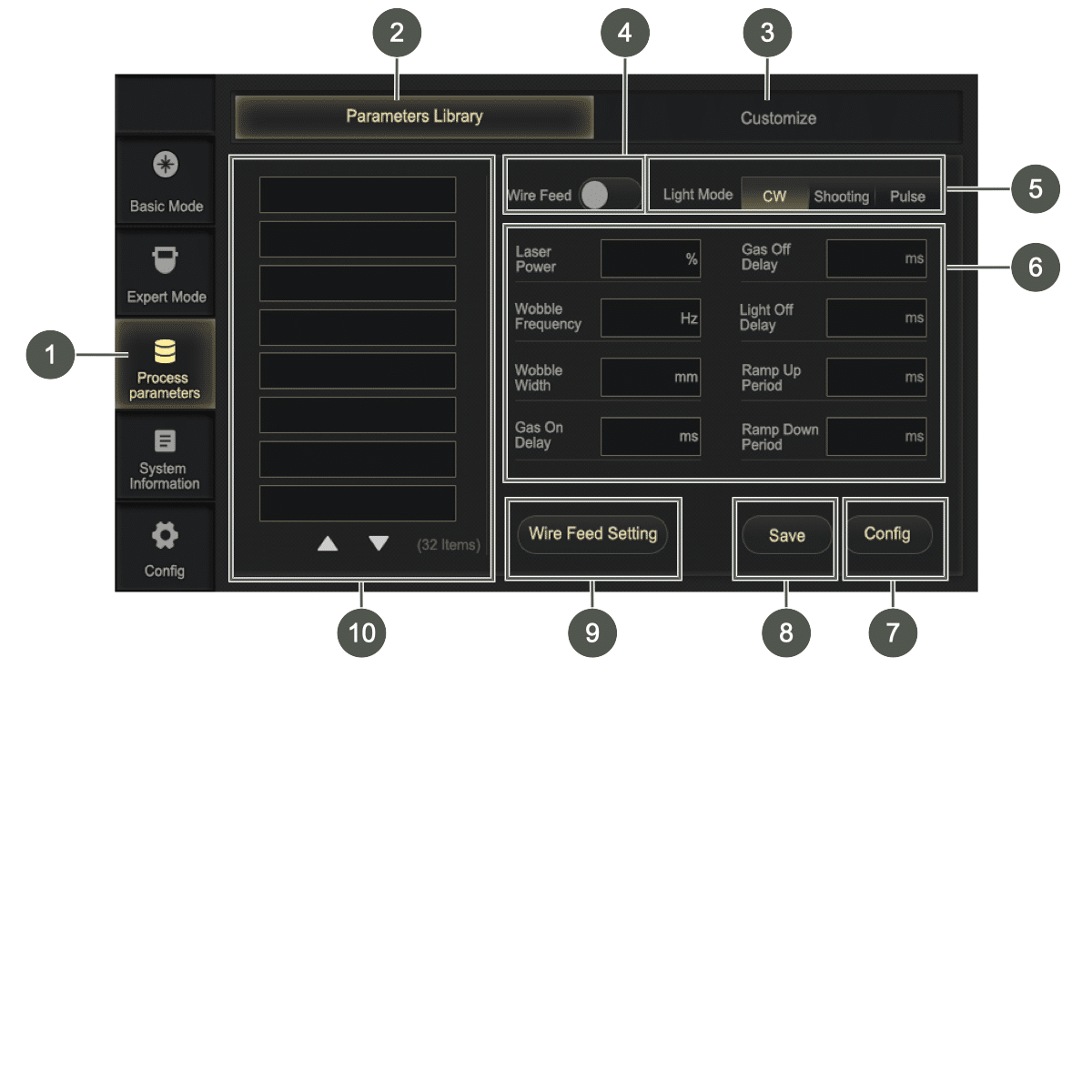
Click on the Process parameters (1) button to open the user interface and create and administer the parameter sets on the Parameters Library (2) and Customize (3) tabs.
Four pages are available on which a total of 32 parameter sets can be saved.
For more information on the parameters, see the Expert Mode section; see Expert Mode.
Parameters Library #
On the user interface of the Parameters Library (2) tab, setting can be made in preset parameter sets.
Customize #
On the user interface of the Customized (3) tab, setting can be made in preset parameter sets.
補足情報#
Administering the parameter sets #
- Click a parameter set (10) in the list to display the parameters.
- Click on the input field next to the parameter (6) to edit the parameter.
- テンキーが表示され、そこで希望の値を入力することができます。
- 「Enter」ボタンをクリックして設定を確定してください。
-
- Click on the Save (8) button to save the changes.
- A dialog box opens.
-

- Click in the input field next to the parameter set name.
- Save the parameter set.
- Save button: The parameter set is updated with the new settings and the existing parameter set name.
- Save as button: The parameter set is saved under the new parameter set name.
- Cancel button: The dialog box closes. No changes are saved.
- Click on the Config (7) button if the selected parameter set is to be used for the current welding settings.

Creating a parameter set #
- Click an empty field in the list of parameter sets.
- Click on the Save button.
- A dialog box opens.
-
- Click in the input field next to the parameter set name.
- Assign a new parameter set name.
- Create a new parameter set by clicking on the Save button.
Deleting a parameter set #
If the maximum number of parameter sets has been reached, the parameter set must be overwritten or deleted.
When saving the parameter set, overwrite the parameter set name or enter the new parameter set name EMPTY and save to delete the parameter set.
System Information #
Click on the System Information button to view the details of the system.
Click on the arrow at the bottom right to view the laser information.

System Information #
The System Information area displays important information such as version information and commercial data:
- Model
- Mainboard S/N
- Torch S/N
- SW version
- HW version
- MCU version
- Laser version
- Wire feeder Version
Normal information #
The following information is displayed In the Normal Information area:
- Order date
- Expired date
- 認証コード
- Machine date
- Machine time
The authorization code acquired through the training course can be entered in the Normal Information to unlock the machine or extend the possible machine hours.
If the expiration date of the software is approaching, a dialog box appears informing the user of the impending expiration.
To ensure uninterrupted use of the device, Service must be contacted (see Importeur/Service) and a new license code must be requested.

Laser Information #

System settings #
You require a service password to access the system settings. The service password is only issued to authorized dealers who have successfully completed the training course at Maxphotonics.
There are no settings here that the user needs to make in order to operate the system.
Operating the wire feeder #
警告#
怪我の危険性
溶接ワイヤの通線や手動での移動を行う際、目の怪我につながる恐れがあります。
- ワイヤーフィーダーのトーチライナーの接続部を直視しないでください。
- トーチライナーの出口を直視しないでください。
- ワイヤ供給ノズルを直視しないでください。
- 安全ゴーグルを着用してください。
|
Figure |
ボタン |
説明 |
|---|---|---|
|
|
On-off button/switch-on button |
Switching on/off of the wire feeder. The button lights up red if the wire feed is switched on. |
|
|
Manual wire feed |
Manual feed of the wire. This is used during welding or when exchanging the wire roll. The button lights up green when the wire feed pushes the wire forward. Automatic wire feed is activated by pushing the button for 5 seconds. To stop the automatic wire feed, press the button briefly. The wire feed can also be activated and controlled via the display on the laser welder (see Expert Mode) or the wire feed switch on the welding torch (see Welding torch). |
|
|
手動引き出しボタン |
Manual withdrawal of the wire. This is used during daily welding or cleaning work. The button lights up green when the wire is withdrawn. |


Cleaning and exchanging wear parts #
Regular inspection and checking of the wear parts by the user is necessary and reduces the occurrence of welding problems and poor welding results, increases the service life and ensures the safety of the user.
This includes:
- Safety glass
- 溶接ノズル
- Wire feed
危険#
Risk of fatal injury from improper changes to the laser welding system
Repairs by unqualified persons and the use of unauthorized spare parts can lead to serious injury from electric shock or burns and even death during operation.
- Repairs to the machine may only be carried out by Maxphotonics.
- Only carry out work on the components described in the “Cleaning and exchanging wear parts” section.
- It is strictly forbidden to disassemble and reassemble the hand-held laser welding system without authorization, as this can lead to electric shock or burns as well as damage to the involved components.
- 許可なく製品を分解すると、保証が無効となります。
警告#
欠陥のあるレーザー溶接システムによる負傷の危険性
不具合のあるレーザー溶接装置を操作すると、重傷を負ったり、レーザー溶接装置に損傷を与えたりする恐れがあります。
- レーザー溶接システムは、故障や損傷がなく、部品の欠落や緩みがない場合にのみ作動させてください。
お知らせ#
Repair work may only be performed by our Service.
Repairs #
- Contact Maxphotonics Service if repairs become necessary (see Importeur/Service).
- Package the product in suitable packaging (original packaging) and send it back.
- If the warranty period of the product has expired or if the scope of warranty is exceeded, the customer is responsible for the repair costs.
- The manufacturer reserves the right to change the design or structure of the products, and the information may be changed without prior notice.
Spare parts #
Contact Service (see Importeur/Service) or visit the online shop of Maxphotonics if you require spare parts.
- ブラウザの検索欄に以下のリンクを入力するか、QRコードをスキャンしてください。
- theo.inc/de/shop/shop-categories/

補足情報#
レーザー溶接機#
警告#
怪我の危険性
Before performing cleaning work, disconnect the device from the line supply.
- Have repair work on the device performed by Maxphotonics only.
補足情報#
Visual inspection of the laser welder #
- Check that all cooling fans rotate smoothly and consistently when switched on.
- Inspect the gas hoses for leaks.
- Check whether the wire feeder module and the insulation have come loose.
- Check whether the loop cable has a defect.
Cleaning the laser welder #
The hand-held laser welder is air-cooled. The ventilation channels and grille must therefore be cleaned regularly and at least every two months.
The user must regularly use a vacuum cleaner and compressed air to vacuum or blow out the dust inside the laser welder.
We recommend cleaning the device once a week with a maximum of 2 bar compressed air.

- Switch off the laser welder at the power switch and disconnect it from the power supply.
- Wait for the laser welder to power down.
- Blow out the laser welder in the upper area and remove coarse contamination.
Cleaning the grille (suction) #
お知らせ#
Clean the grille on the hand-held laser welding system regularly, at least every three months, to remove dust and contamination from the air inlet.
- Switch off the laser welder at the power switch and disconnect it from the power supply.
- Wait for the laser welder to power down.
- Set the system down on the left side on a soft surface.
- Unscrew 6 cross-head screws from the grille on the underside.
- Remove the grille.
- Suction the three round ventilation openings and the oblong opening.
- Blow out the ventilation openings with lightly compressed air.
- Clean the housing with a clean towel.
溶接トーチ#
補足情報#
Cleaning the welding torch #
お知らせ#
Clean the welding torch with a dry towel, not with compressed air.
- Remove contamination from the welding torch with a clean towel.
Changing the safety glass #
注意#
Damage to the device
The optical output of the hand-held laser welder is transmitted through a safety glass with an anti-reflective coating. Any dust or dirt on the safety glass can cause serious damage, resulting in burning of the hand-held laser welder or malfunction of downstream optical devices.
- Replace the safety glass at regular intervals depending on the use of the laser welder.
お知らせ#
Do not touch the safety glass directly with your fingers. Direct contact with the skin can contaminate the safety glass and render it unusable.
If soot forms during the welding process or the laser loses power, this may be due to a contaminated safety glass.

|
1 |
ローレットネジ |
2 |
安全ガラス収納部 |
|
3 |
Shaft |
4 |
Sealing ring |
|
5 |
Safety glass |
|
|
- Switch off the laser welder at the power switch and disconnect it from the power supply.
- Release the knurled screw (1).
- Pull the safety glass compartment (2) out of the welding torch.
- Mask the shaft (3) of the safety glass compartment with masking tape to protect the optics from dirt.
- Remove the sealing ring (4).
- Tilt out the safety glass (5).
- Insert a new safety glass and wipe with the film on the safety glass compartment.
-
- Insert the sealing ring.
- Pull off the masking tape.
- Insert the safety glass compartment into the welding torch.
- Tighten the knurled screw.

ワイヤフィーダー#
補足情報#
Visual inspection of wire feeder #
Before operating the wire feeder, check the following components for damage:
- Control cable and connector
- Power supply and wire feed button functionality
- Brake mechanism of castors
- Torch liner (kinks and damage)
Visual inspection of wire feed rollers and pressure rollers #
- Check the grooved profile of the wire feed rollers and the wear condition of the pressure rollers.
- Ensure that the grooves are free of contamination. Replace if very worn.
Visual inspection of the torch liner #
- Check the connections of the torch liner.
- Check the torch liner for damage, e.g., for kinks.
- Check the torch liner for blockages.
Checking the motor #
Listen for unusual noises emanating from the motor.
Cleaning the wire feeder #
At least once per month, clean the device with a dry cloth and vacuum it out.
Cleaning the torch liner #
Use compressed air to remove minor blockages caused by metal chips.
Help with faults #
お知らせ#
Contact our Service if you are unable to perform the work yourself.
|
Fault |
Cause |
Elimination |
|---|---|---|
|
Laser does not emit. |
The safety key is not inserted and turned to position 1. |
Insert the safety key and turn to position 1 (see Safety key). |
|
Laser is losing power or produces soot. |
The safety glass is contaminated. |
Change the safety glass (see Schutzglas wechseln). |
|
Laser is not enabled. |
The loop cable is not connected. |
Connect the loop cable (see Setting up the laser welding system and Connecting the laser welder). |
|
The pilot laser is not enabled when workpiece contact is made. |
The loop cable is not connected. |
For more information on connecting the laser welding system, see Setting up the laser welding system and Connecting the laser welder). |
補足情報#
System messages #
|
メッセージ |
Cause |
Elimination |
|---|---|---|
|
|
The maximum number of parameter sets has been reached. |
Overwrite or delete the parameter sets (see Administering the parameter sets). |
|
|
The expiration date of the software has been or will (soon) be reached. |
Contact Maxphotonics Service (see Importeur/Service). |
|
|
The software update is performed. |
|
|
|
The authorization code is invalid. |
Contact Maxphotonics Service (see Importeur/Service). |
|
|
The authorization code is incorrect. |
|
|
|
The power supply has a ground fault. |
Check the connections (see Setting up the laser welding system). |
|
|
The emergency stop switch is active. |
Deactivate the emergency stop switch (see Emergency stop switch). |
|
|
The service password is incorrect. |
|
|
|
The laser welding system is contaminated. |
Clean the laser welding system (siehe Reinigung und Austausch der Verschleißteile). |
|
|
The key switch is locked. |
Turn the safety switch to position 1 (see Safety key). |


Warning #
The Warning tab in the Expert Mode menu displays all alarm information generated by the laser welding system (see Warning tab).
You are made aware of problems or potential problems that require troubleshooting.
Transport and storage #
お知らせ#
Package the machine for transport and storage in such a way that it is protected against impacts and humidity. The original packaging offers optimal protection.
Ensure compliance with the permissible ambient conditions specified in the technical data.
注意#
怪我の危険性
Accessibility of the machine to children and unauthorized persons during storage may result in injuries.
- Store the machine out of the reach of children and unauthorized persons.
Ensure that the assembly location is safe, protected and dry. For more information, see the technical data (see Laserschweißanlage and Drahtvorschubgerät).
Disposal #
Dispose of the machine and its components in accordance with the applicable national regulations.
Always dispose of packaging in an environmentally friendly manner.
Declaration of conformity #


Technical data #
補足情報#
Dimensions #


Laser welding system #
|
|
MA1-35 |
MA1-45 |
MA1-65 |
MA1 Ultra |
|---|---|---|---|---|
|
重量 |
29±3 |
38±3 |
39±3 |
42±3 |
|
Input power (100% power) |
3000 W |
4800 W |
6000 W |
6000 W |
|
Output power |
~800 W |
~1200 W |
~1500 W |
~2000 W |
|
Laser shaft length |
1070 – 1090 nm |
|||
|
Maximum modulation frequency |
10 kHz |
|||
|
Laser switch-off duration |
0 – 100 ms |
|||
|
Sound pressure level |
85 db(A)
|
|||
|
Penetration depth for stainless steel |
Up to ~3.5 mm |
Up to ~4.5 mm |
Up to ~6.5 mm |
Up to ~8.0 mm |
|
Penetration depth for steel |
Up to ~3.5 mm |
Up to ~4.5 mm |
Up to ~6.5 mm |
Up to ~8.0 mm |
|
Penetration depth for aluminum |
Up to ~3.0 mm |
Up to ~4.0 mm |
Up to ~5.5 mm |
Up to ~6.0 mm |
補足情報#
General characteristic parameters #
|
Properties |
Test conditions |
Min. |
Nom. |
Max. |
Unit |
|---|---|---|---|---|---|
|
Operating voltage |
|
200 |
220 |
240 |
VAC |
|
Ambient operating temperature |
|
0 |
|
40 |
°C |
|
Relative ambient humidity |
|
10 |
|
85 |
% |
|
Cooling method of the laser |
Heat dissipation by direct air cooling |
||||
|
Cooling method of the torch |
Gas cooling of the fiber optic connector and optics |
||||
|
Storage temperature |
|
-10 |
|
60 |
°C |
Input #
|
Designation |
Value |
Unit |
|---|---|---|
|
Laser power |
1500 |
W |
|
Unfocused beam size |
5.495 |
mm |
|
Divergence angle |
27.5 |
mrad |
|
Exposure time |
1 |
s |
Output #
|
|
MA1-35 |
MA1-45 |
MA1-65 |
MA1 Ultra |
|---|---|---|---|---|
|
NOHD値 |
118 m |
144 m |
178 m |
282 m |
|
NHZ |
22 m |
27 m |
34 m |
53 m |
|
MPE (EMZB) |
70.7 Wm² |
|||
Optical properties #
|
Properties |
Test conditions |
Min. |
Nom. |
Max. |
Unit |
|||
|---|---|---|---|---|---|---|---|---|
|
Operating type |
CW/modulated |
|||||||
|
Polarization |
Randomized |
|||||||
|
出力 |
100% CW | Ambient temperature 26 °C |
700 1000 1400 |
800 1200 1500 |
|
W |
|||
|
Power control range |
1% | Ambient temperature 26 °C |
10 |
|
100 |
% |
|||
|
Central wavelength |
100% CW |
|
1080 |
|
nm |
|||
|
Electro-optical efficiency |
10 – 100% linear adjustment |
|
27 |
|
% |
|||
|
Spectral bandwidth (3 dB) |
100% CW |
|
3 |
5 |
nm |
|||
|
Short-term power stability |
100% CW > 1 h |
|
2 |
|
% |
|||
|
M2 |
100% CW |
|
1.3 |
|
|
|||
|
Laser switch-on time ON |
10% → 90% power |
|
50 |
100 |
私たち |
|||
|
Laser switch-off time |
90% → 10% output |
|
50 |
100 |
私たち |
|||
|
Fiber break detection |
|
|
|
20 |
ms |
|||
|
Displayed power of red light |
100% CW |
300 |
|
1000 |
uW |
|||
|
Length of armored cable with optical fibers |
MA1-35 |
4.35 |
m |
|||||
|
MA1-45, MA1-65, Ultra |
5.6 |
m |
||||||
|
Bending radius of optical fiber armored cable |
|
200 |
|
|
mm |
|||
|
Laser output connector |
QCS integrated on the fiber |
|||||||
|
Continuous light output time (S) |
ON 120S, OFF 6S |
|||||||
|
NOHD値 |
100% output power 2 m distance |
|
|
0.183 |
W/mm2 |
|||
ワイヤフィーダー#
|
重量 |
13±3 |
|
Supply voltage |
24 V DC |
|
Ambient conditions |
No vibration, no impact |
|
Ambient operating temperature |
5 – 50 °C |
|
Ambient humidity |
< 90% RH |
|
Temperature of the storage environment |
-15 to 85 °C |
|
Maximum wire roller weight |
25 kg |
|
Voltage supply |
External (of MA1) |
Welding process parameters #
補足情報#
Process parameters for hand-held laser welding #
お知らせ#
Note the process parameters for butt welding, fillet welding, lap welding, etc.
|
材料 |
Welding position |
Thickness |
Laser power |
Width |
Wobble frequency |
Focus setting |
Air volume flow |
|---|---|---|---|---|---|---|---|
|
mm |
W |
mm |
Hz |
mm |
l/min |
||
|
Carbon steel (Q235B) |
Fillet weld |
1 |
500 |
1 – 2 |
60~80 |
-1~1 |
8 – 10 |
|
Fillet weld |
1.5 |
650 |
2 |
60~80 |
-1~1 |
8 – 10 |
|
|
Fillet weld |
2.5 |
800 |
2.5 |
50~70 |
-2~1 |
8 – 10 |
|
|
Stainless steel (SUS304) |
Fillet weld |
1 |
300 |
1 – 2 |
40~70 |
-1~1 |
8 – 10 |
|
Fillet weld |
2 |
550 |
2 |
40~70 |
-1~1 |
8 – 10 |
|
|
Fillet weld |
2.5 |
800 |
2.5 |
40~70 |
-2~1 |
8 – 10 |
|
|
Galvanized sheet metal |
Fillet weld |
1 |
300 |
1 – 2 |
60~80 |
-1~1 |
8 – 10 |
|
Fillet weld |
2 |
400 |
2 |
60~80 |
-1~1 |
8 – 10 |
|
|
Fillet weld |
2.5 |
500 |
2.5 |
50~70 |
-2~1 |
8 – 10 |
|
|
Aluminum alloy (Al6061) |
Fillet weld |
1 |
600 |
1 – 2 |
60~80 |
-1~1 |
8 – 10 |
|
Fillet weld |
2 |
800 |
2 |
60~80 |
-1~1 |
8 – 10 |
Remarks #
- The welding position is dragging.
- Welding shielding gas: Nitrogen (purity 99.99%).
- The power percentage is 10 – 100%, the wobble width is 0 – 4 mm (2 – 3 mm is recommended), the wobble frequency is 0 – 220 Hz (40 – 80 Hz is recommended for manual welding, and the gas flow rate is 8 – 10 l/min). Provided that other parameters remain unchanged, the laser power must be increased accordingly if the wobble width or welding speed is increased.
- Welding speed = welding length/welding time (welding speed is influenced by human factors, welding speed is approximately 10 – 20 mm/s). Due to the different welding processes used by customers (air pressure, manual speed, degree of deflection, welding angle), this data is for reference only.
- Condition for the activation of D mode (MA1-35): D mode can be activated if the output is ≥ 90%.
- Welders must comply with all laser safety measures (see Laserschutzmaßnahmen). Welders must wear laser safety goggles. Hand-held laser welding must be carried out in an approved room with laser safety measures. Non-welding personnel and combustible materials should not be in the room and a fire extinguisher should be placed near the welding area.
Process parameters for hand-held laser welding – wire feed butt joint #
お知らせ#
Note the process parameters for stack welding, fillet welding, lap welding, etc.
|
材料 |
Material thickness |
Wire feed speed |
Laser power |
Wobble width |
Wobble frequency |
Focal plane |
Air volume flow |
Welding consumables |
Wire diameter |
Effect |
|---|---|---|---|---|---|---|---|---|---|---|
|
mm |
mm/s |
W |
mm |
Hz |
mm |
l/min |
/ |
mm |
Penetration |
|
|
Carbon steel (S235JR) |
1 |
12~15 |
350 |
2 |
40~80 |
2~-4 |
15~20 |
|
0.8 – 1.0 |
Penetration |
|
2 |
8~10 |
450 |
2 |
40~80 |
1~3 |
15~20 |
|
0.8 – 1.0 |
Penetration |
|
|
Stainless steel (1.4301) |
1 |
12~18 |
300 |
1.2 |
40~80 |
2~-4 |
15~20 |
|
0.8 – 1.2 |
Penetration |
|
2 |
8~10 |
400 |
1.8 |
40~80 |
1~3 |
15~20 |
|
0.8 – 1.2 |
Penetration |
|
|
Aluminum alloy (Al6061) |
1 |
12~18 |
600 |
2 |
40~80 |
1~-1 |
15~20 |
AlMg |
1.2 |
Penetration |
|
2 |
12~15 |
750 |
2 |
40~80 |
1~3 |
15~20 |
AlMg |
1.2 |
Penetration |
Remarks #
- The welding position is dragging.
- Welding shielding gas: Nitrogen (purity 99.99%).
- The power percentage is 10 – 100%, the wobble width is 0 – 4 mm (2 – 3 mm is recommended), the wobble frequency is 0 – 220 Hz (40 – 80 Hz is recommended for manual welding, and the gas flow rate is 8 – 10 l/min). Provided that other parameters remain unchanged, the laser power must be increased accordingly if the wobble width or welding speed is increased.
- Welding speed = welding length/welding time (welding speed is influenced by human factors, welding speed is approximately 10 – 20 mm/s). Due to the different welding processes used by customers (air pressure, manual speed, degree of deflection, welding angle), this data is for reference only.
- Condition for the activation of D mode (MA1-35): D mode can be activated if the output is ≥ 90%.
- Welders must comply with all laser safety measures (see Laser safety measures). Welders must wear laser safety goggles. Hand-held laser welding must be carried out in an approved room with laser safety measures. Non-welding personnel and combustible materials should not be in the room and a fire extinguisher should be placed near the welding area.
