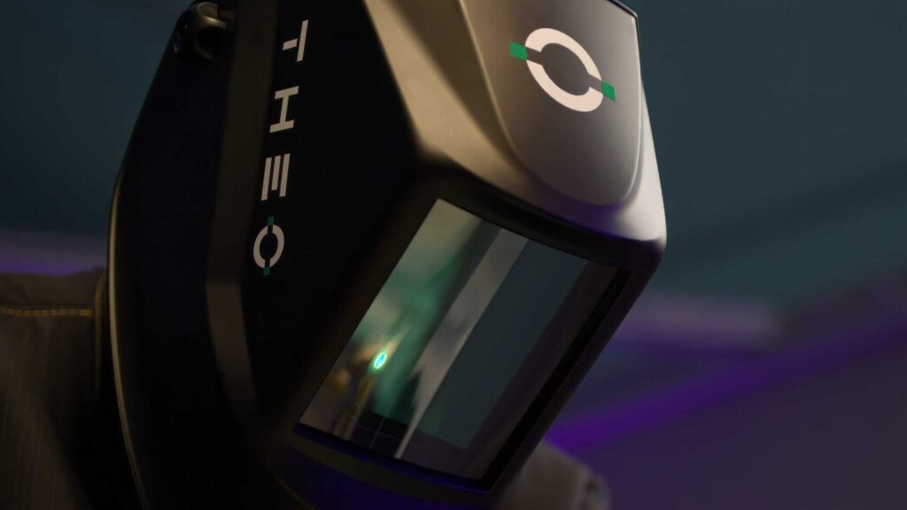
USER MANUAL: PLEASE READ AND UNDERSTAND ALL INSTRUCTION BEFORE USE
EN ISO 16321-1:2022
EN ISO 16321-2:2021
AS/NZS 1337.1:2010
AS/NZS 1338.1:2012
1. SAFETY PRECAUTIONS #
Symbol Usage #
i Protect yourself and others from injury — read, follow, and save these important safety precautions and operating instructions.
i DANGER! − Indicates a hazardous situation which, if not avoided, will result in death or serious injury. The possible hazards are shown in the adjoining symbols or explained in the text.
i Indicates a hazardous situation which, if not avoided, could result in death or serious injury. The possible hazards are shown in the adjoining symbols or explained in the text..

This group of symbols means Warning! Watch Out! ELECTRIC SHOCK, MOVING PARTS, and HOT PARTS hazards. Consult symbols and related instructions below for necessary actions to avoid the hazards.
NOTICE – Indicates statements not related to personal injury.
NOISE can damage hearing.
Noise from some processes or equipment can damage hearing.
Wear approved ear protection if noise level is high.
THE HELMETS do not provide unlimited eye, ear, and face protection.
Arc rays from the welding process produce intense visible and invisible (ultraviolet and infrared) rays that can burn eyes and skin. Sparks fly off from the weld.
- Use impact resistant safety spectacles or goggles and ear protection at all times when using this welding helmet.
- Do not use this helmet while working with or around explosives or corrosive liquids.
- Do not weld in the overhead position while using this helmet.
- Inspect the filter frequently. Immediately replace any scratched, cracked, or pitted cover lenses or filter.
- Lens and retention components must be installed as instructed in this manual to ensure compliance with protection standards.
READ INSTRUCTIONS.
- Read and follow all labels and the User Manual carefully before installing, operating, or servicing unit. Read the safety information at the beginning of the manual and in each section.
- Use only genuine replacement parts from the manufacturer.
- Perform installation, maintenance, and service according to the User Manual, industry standards, and national, state, and local codes.
Warnings #
It is the user’s responsibility to ensure that the filter used to protect the eye from laser radiation matches the laser source used. Not wearing eye protection or choosing inappropriate eye protection device can result in injury or blindness!
Please refer to the applicable standards and ask the person responsible for laser safety about how to choose the most appropriate eye protection device for the laser source you are using.
Laser welding helmets are not designed to protect the eyes from intentional, continuous or repeated direct exposure to laser beams, but to prevent accidental, temporary exposure to scattering and diffuse laser light. In addition, both the limit value and resistance tests are based on a maximum exposure time of 5 seconds.
Laser welding helmets are marked with the wavelength range and associated degree of protection provided, in accordance with European standard EN 207:2017.
Users must comply with the following instructions:
- Please consult the laser safety officer about appropriate eye protection equipment for the laser source used.
- Check the marking on the eye protection device and ensure that the specifications of the wavelength and protection level printed on the device are appropriate for the laser source used.
- Check the light transmittance specifications of the filter in the specification sheet.
- People working in areas where there is a risk of exposure to laser radiation must wear laser protection device.
- The light transmittance of the lens is less than 20%, the light at the workplace must be increased when using this eyewear.
- The recognition of warning lights or warning signals can be impaired because of the color filters.
- Do not use this eye protection device while driving, engaging in recreation or sports activities or any other activities that they are not designed for.
- Keep these instructions with a protective device
- Please refer to the user manual for technical information and performance of the eye protection device you own.
- Filters shall not be interchangeable in the frame. They are only used for the laser welding helmet.
- Filters in the laser welding helmet against laser radiation shall not be exchanged by non-professionals.
Unauthorized modifications and replacement parts will void the warranty and expose the user to the risk of personal injury.
Safety Of Battery Use #
- Remove and immediately recycle or dispose of used batteries according to local regulations and keep away from children. Do NOT dispose of batteries in household trash or incinerate.
- Even used batteries may cause severe injury or death.
- Call a local poison control center for treatment information.
- Non-rechargeable batteries are not to be recharged.
- The nominal battery voltage 3V.
- Do not force discharge, recharge, disassemble, heat above 140℉ or incinerate. Doing so may result in injury due to venting, leakage or explosion resulting in chemical burns.
- Ensure the batteries are installed correctly according to polarity (+ and -).
- Do not mix old and new batteries, different brands or types of batteries, such as alkaline, carbon-zinc, or rechargeable batteries.
- Remove and immediately recycle or dispose of batteries from equipment not used for an extended period of time according to local regulations.
- Always completely secure the battery compartment. lf the battery compartment does not close securely, stop using the product, remove the batteries, and keep them away from children.
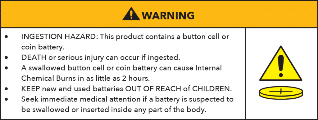
This symbol means: INGESTION HAZARD: This product contains a button cell or coin battery.
Specifications #
| VIZ-R2 | VIZ-R2 PLUS | |
| Helmet Shell | Special Nylon (Flame Retardant) | Special Nylon (Flame Retardant) |
| Filter Dimension | 4.49 x 5.24 x 0.39 in. / 114 x 133 x 10 mm | 4.49 x 5.24 x 0.35 in. / 114 x 133 x 9 mm |
| View Size | 4.17 x 4.72 in. / 106 x 120 mm | 3.94 x 2.36 in. / 100 x 60 mm |
| Shell Front Plate | Carbon Fiber | Carbon Fiber |
| Filter | Coated glass + Laser Filter | LCD with Laser Filter |
| Shade No. | W2.5 | W2.5~5 |
| Low Battery Indicator | – | Yes |
| Visible Light Transmission | 20% (W2.5) | 25% (W2.5) / 15% (W3) / 10% (W3.5) / 5% (W4) / 2% (W5) |
| Red Light (650nm) Transmittance | >5% | >15% |
| Wavelength 900 – 1000 nm | OD6+ | OD6+ |
| Wavelength 1000 – 1100 nm | OD7+ | |
| Wavelength 1000 – 1080 nm | OD7+ | |
| Interlock Function | Included | Included |
| Interlocking Device Power Supply | 1 replaceable CR2450 Lithium Battery | 1 replaceable CR2450 Lithium Battery |
| Laser Filter 900 – 1080 nm | D LB7 IR LB8 CE | D LB7 IR LB8 CE |
| Protection shield (Carbon) 900 – 1100 nm | D LB7 IR LB8 CE | D LB7 IR LB8 CE |
| Outer Protection Lens | Part No: PL-5002 Size: 4.49 × 5.24 × 0.04 in. (114 × 133 × 1 mm) | Part No: PL-5002 Size: 4.49 × 5.24 × 0.04 in. (114 × 133 × 1 mm) |
| Inner Protection Lens | – | Part No: PL-5001 Size: 4.16 × 2.59 × 0.04 in. (105.8 × 65.8 × 1 mm) |
| Operating Temperature | 14 ℉ to 149 ℉ -10 ℃ to +65 ℃ | 14 ℉ to 149 ℉ -10 ℃ to +65 ℃ |
| Storing Temperature | -4 ℉ to 185 ℉ -20 ℃ to +85 ℃ | -4 ℉ to 185 ℉ -20 ℃ to +85 ℃ |
| Warranty | 1 Year | 1 Year |
OPERATING INSTRUCTIONS #
ONLY APPLICABLE FOR THE VIZ-R2 PLUS
Helmet Controls #
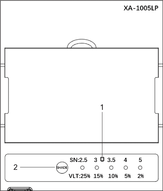
- Low Battery Indicator
- Variable Shade Control
Filters shall not be interchangeable in the frame. They are only used for the laser welding helmet.
Low Battery Indicator #
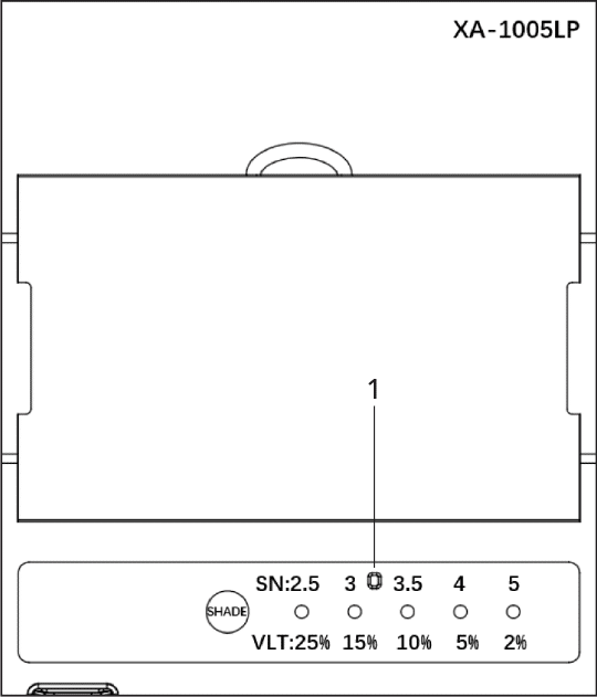
- Low Battery Indicator
The red LED light is on, replace the battery as soon as possible, install one new CR2032 lithium battery.
The Filter consumes less than 1 microamp of battery power when in the sleep mode.
Filters shall not be interchangeable in the frame. They are only used for the laser welding helmet.
Variable Shade Control (No. 2.5~5) #

2. Variable Shade Control (No. 2.5~5)
Use the control to adjust the shade in the darkened state.
Start at the highest setting and adjust lighter to suit the welding application and your personal preference.
Filters shall not be interchangeable in the frame. They are only used for the laser welding helmet.
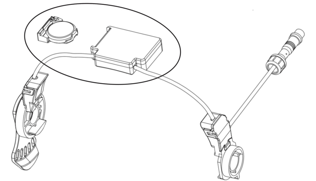
INTERLOCK FUNCTION #
Detection and Prompt
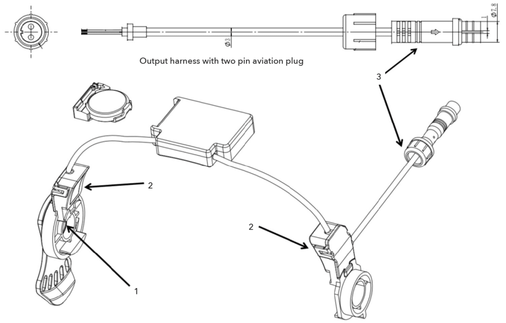
- Rotation position detection: Position 1 is used to detect whether the helmet is flipped down.
- Interlock control components include human skin capacitance detection: Position 2 is used to detect whether the helmet is worn on the head.
- System control and output circuit: Position 3 indicates that the output is connected to the controlled unit.
Buzzer sounds: Indicate the working status, non-working status, battery low voltage, warning, etc.
Interlock Function Instructions:
- Put on the helmet, adjust headgear ratchet knob to a comfortable position. When flipping down the helmet, the internal buzzer sounds for about 1 second [long beep], and the output relay is closed, which means that it is ready to weld.
- If the helmet is taken off or flipped up (either of the two conditions is met), the internal buzzer sounds for about 0.5 seconds [short beep], and the output relay is disconnected, which means that the welding is currently prohibited.
- Low battery warning: The battery voltage is lower than 2.65V. The buzzer rings two consecutive sounds for warning.
Control Parameters
| Product Power Supply | CR2450 (600mAH) |
| Detection Form | Capacitive proximity detection (Detects whether the helmet is put on) Magnetic proximity detection (Detects whether the mask is down/raised) |
| Output Interface | Self-holding relay |
| Closing Condition of Relay Switch | Detection is valid at the same time (capacitance and magnetic) |
| Disconnection of Relay Switch | Either (capacitance or magnetism) is invalid |
Replacing the Battery #
The Interlock unit is powered by one 2450 lithium battery.
Low battery warning: the battery voltage is lower than 2.65V, the buzzer rings two consecutive sounds for warning.
Be sure Positive (+) side of the battery faces up (toward inside of helmet).
ADJUSTING HEADGEAR #
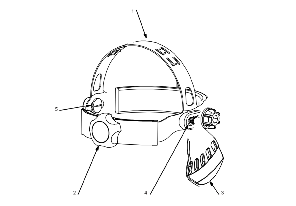
There are four headgear adjustments: headgear top, tightness, angle adjustment, and distance adjustment.
- Headgear Top Adjustment
Adjusts headgear for proper depth on the head to ensure correct balance and stability. - Headgear Tightness Adjustment
To adjust, turn the adjusting knob located on the back of the headgear left or right to desired tightness. - Angle Adjustment
Slots on the right side of the headband provide adjustment for the forward tilt of the helmet. To adjust, lift and reposition the control arm to the desired position. - Distance Adjustment
- Headgear Screw
Adjusts the distance between the face and the lens. To adjust, loosen headgear screws and slide headgear forward or backward to one of the three slots on the slider. Tighten screws. (Both sides must be equally positioned for proper vision.
REPLACING THE PROTECTION LENS #
i Never use the Filter without the inner and outer protection lens properly installed. Welding spatter will damage the Filter and void the warranty.
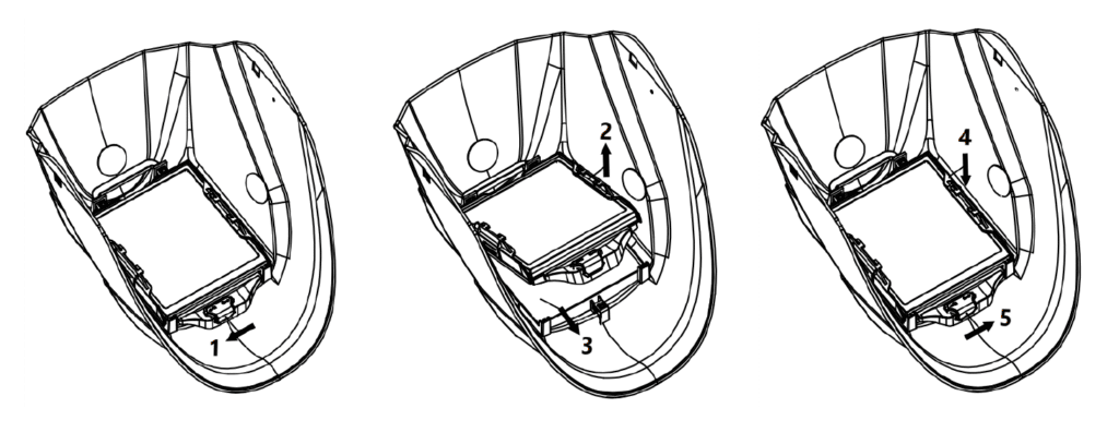
- Slide the frame lock to the left to unlock the filter assembly.
- Lift up the frame assembly.
- Remove protective lens and install new one.
- Press down the frame assembly to reset.
- Slide the frame lock to the right to lock the filter assembly and helmet.
REPLACING THE BATTERY #
The VIZ-R2 PLUS is powered by one 2032 lithium battery. If battery power is low, install one new CR2032 lithium battery.
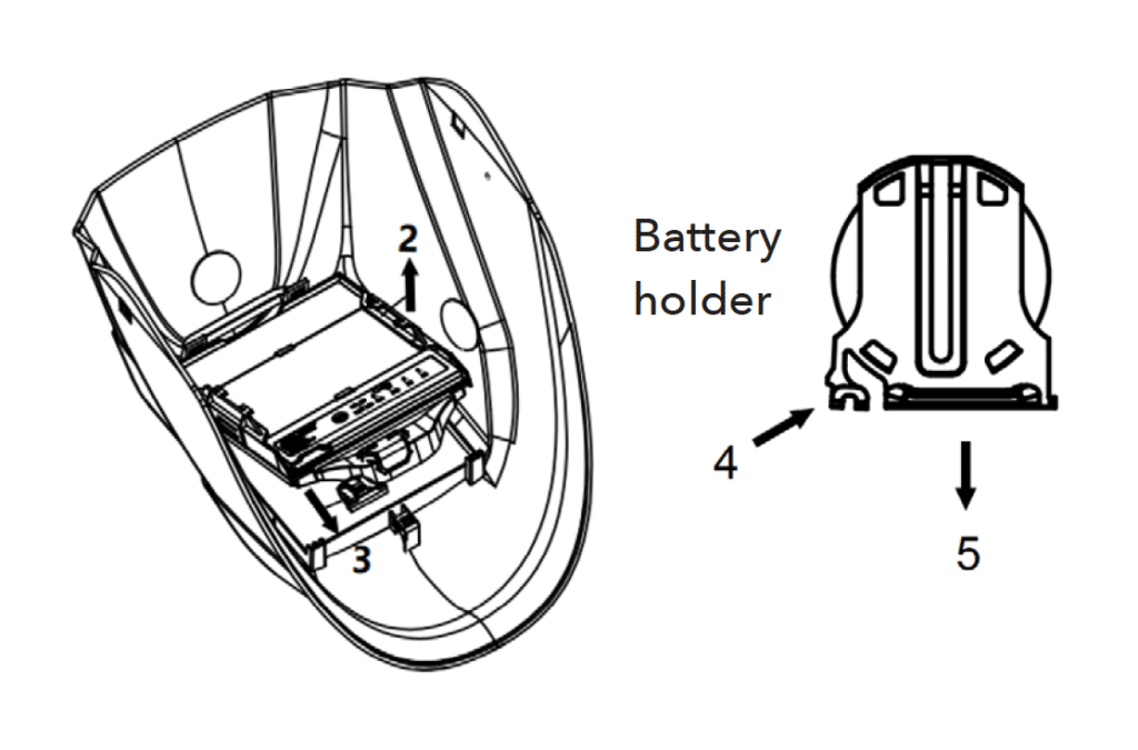
2. Lift up the frame assembly.
3. Remove the frame assembly.
4. Pinch one end of the battery holder.
5. Pull the battery holder out, replace the battery, and reinsert the battery holder.
INSTALLING OPTIONAL MAGNIFYING LENS #
- Optional Magnifying Lens
Slide magnifying lens into the helmet retaining brackets as shown. Align the magnifying lens with the filter assembly.
To prevent lens fogging, install flat side of magnifying lens toward the filter.
MAINTENANCE #
NOTICE – Never use solvents or abrasive cleaning detergents.
NOTICE – Do not immerse the lens assembly in water.
The helmet requires little maintenance. However, for best performance clean helmet after each use. Using a soft cloth dampened with a mild soap and water solution, wipe the cover lenses clean. Allow to air dry. Occasionally, the protection lens should be cleaned by gently wiping with a soft, dry cloth.
MARKINGS AND STANDARDS APPLIED #
Marking #
Passive laser welding filter with laser protection (LPF5-3)
16321 THEO W2.5 900-1080 D LB7 IR LB8 THEO CE according to EN 207:2017
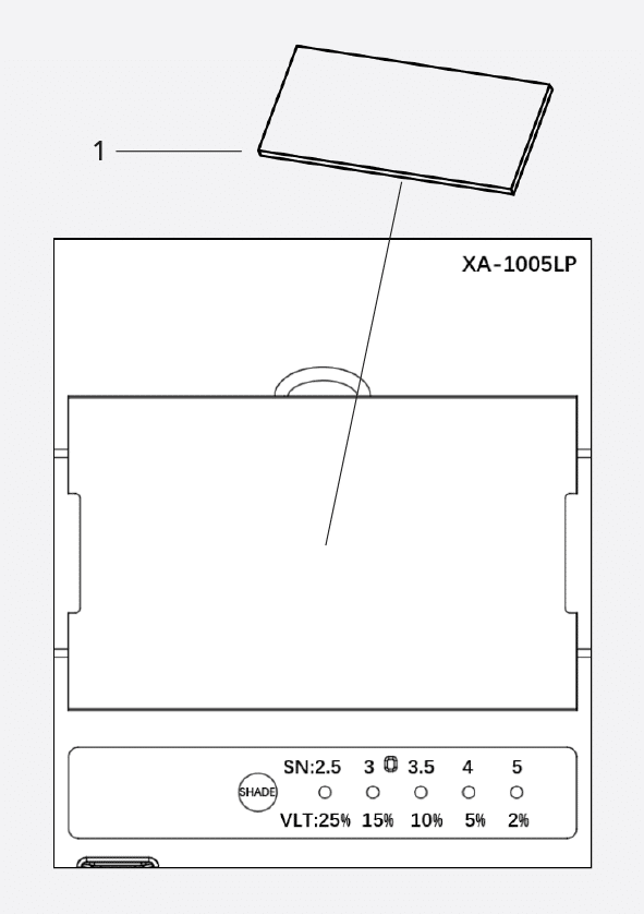
Adjustable darkening filter with laser protection (XA-1005LP)
16321 THEO W2.5/3/3.5/4/5 V2 900-1080 D LB7 IR LB8 CE according to EN 207:2017
Protection shield (Carbon)
16321 THEO W15 900-1100 D LB7 IR LB8 CE
according to EN 207:2017 with
- 900 – 1100: Applicable laser wave length range;
- THEO: Manufacturer code;
- D LB7: Laser protection rating of LB7 for mode “D” (CW mode) according to EN 207:2017, clauses 3.3, Table 1 and 6.1;
- IR LB8: Laser protection rating of LB8 for mode “I” ( HPP mode) “R” ( Q mode) according to EN 207:2017, clauses 3.3, Table 1 and 6.1;
- CE: CE as per PPE Regulation (EU) 2016/425, Article 17 required for Cat. II products
The letter “D” denotes a CW laser having a pulse length of >0.25 s.
The letter “I” denotes a pulsed laser, having a pulse length between 1 μs and 0.25 s
The LB rating specifies the damage threshold of the filter material at maximum power or energy density.
The Helmet does not only absorb (filter) laser light of a given wavelength, but is also be able to withstand a direct hit from the laser without breaking or melting, for the specified time period of >5 s in CW mode or for 50 pulses (s. Annex: Test Report).
PARTS LIST: VIZ-R2 #
- Helmet shell (Polyamide)
- Block nut
- Outer protection lens
- AWF Lock pin
- Filter frame
- AWF frame lock
- Filter
- H-slot tapping screw
- U-shaped stopper
- Headband slider (with 3 slots)
- Headband adjusting buttons
- Headband tightness adjusting knob
- Headgear connector
- Headband adjusting buttons
- Block washer
- Headgear body
- Segmental position plate
- Sweatband
- Dowel
- Metal rivet
- Insulating tape (circular)
- Protection shield (Carbon)
- Segmental position plate
- Magnet
- Bracket cover plate
- Support PCB – right side
- Bracket – right side
- Induction copper sheet
- Battery holder
- Battery CR2450
- Controller cover
- Main control PCB
- Controller base
- Spring connection wire
- Bracket – Left side
- Support PCB – left side
- Output harness (Two pin aviation plug)
PARTS LIST: VIZ-R2 PLUS #
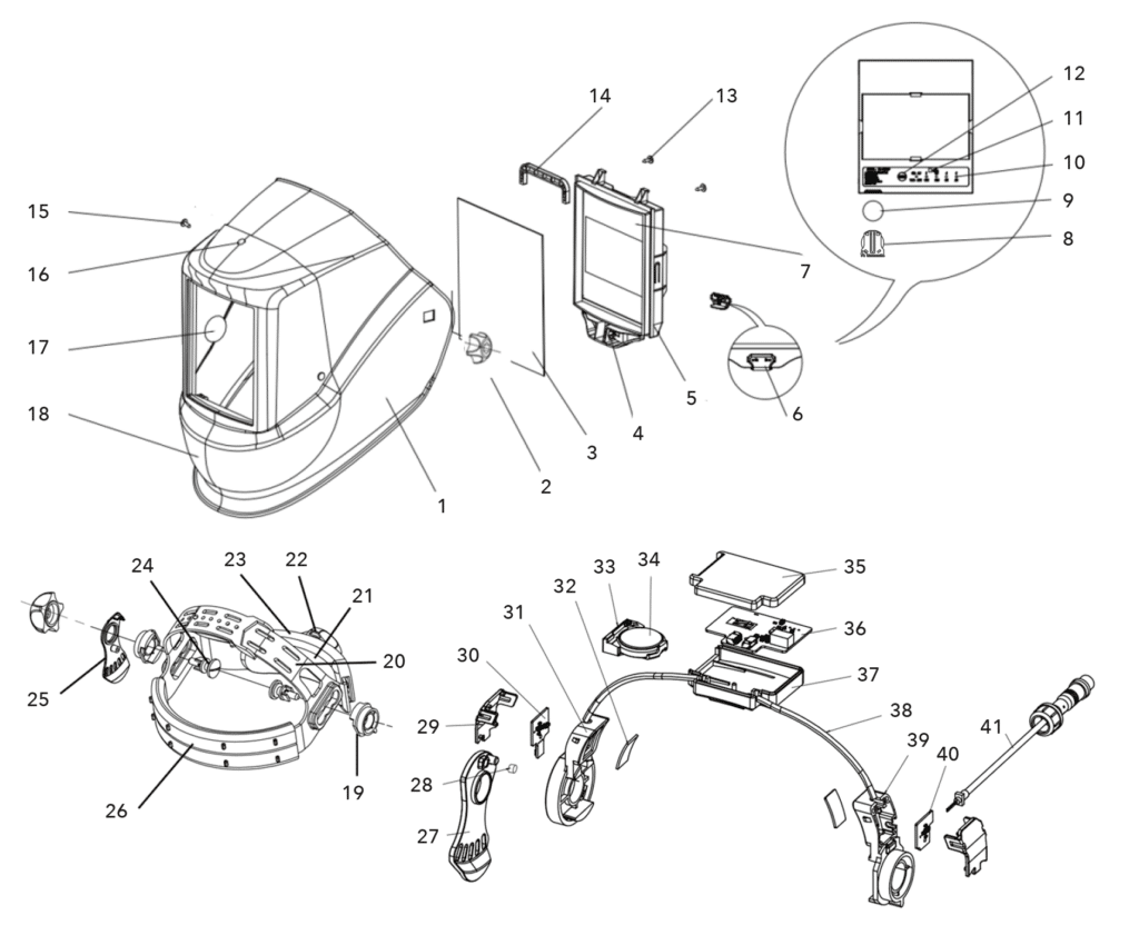
- Helmet shell (Polyamide)
- Block nut
- Outer protection lens
- AWF Lock pin
- Filter frame
- AWF frame lock
- AWF
- Battery holder
- Battery
- Indicator lamp
- Low battery indicator
- Shade button
- H-slot tapping screw
- U-shaped stopper
- Dowel
- Metal rivet
- Insulating tape (circular)
- Protection shield (Carbon)
- Block washer
- Headgear slider (with 3 slots)
- Headgear screw (with 3 slots)
- Headband tightness adjusting knob
- Headgear connector
- Headband adjusting buttons
- Segmental position plate (on right)
- Sweatband
- Segmental position plate
- Magnet
- Bracket cover plate
- Support PCB- right side
- Bracket – right side
- Induction copper sheet
- Battery holder
- Battery CR2450
- Controller cover
- Main control PCB
- Controller base
- Spring connection wire
- Bracket – Left side
- Support PCB – left side
- Output harness (Two pin aviation plug)
